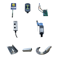
of the Magnetic Limit Switch. Note that the mounting bracket is designed to allow for some adjustment once the
optimal location is identified and the bracket is secured with screws.
4. The next step will be to connect the Wired Component to the control board in the control box. Remove the four
screws that secure the gel pad to the control box. BE CAREFUL The connector and ribbon are fragile and will be
very difficult to successfully reattach. The Gel pad can be placed in the side of the control box while attaching
the wires for the magnetic limit switch (see figure 15).
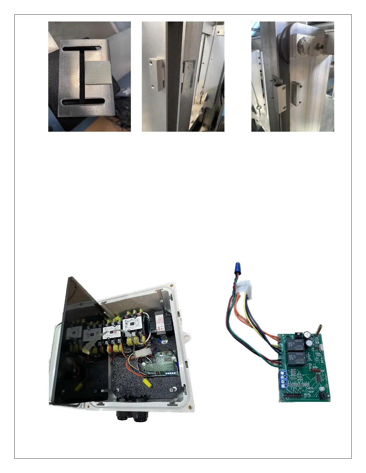
5. For reference, the figure 16 below show the Control Board, CB, outside the control box. Figure 15 shows the CB
installed inside the control box. There are 3 wires (red, green, black) coming from the middle edge of the control
board. These wires are called the “limit wires.” They connect to the Magnetic Limit Switches. The other ends of
these wires are joined together with a blue wire nut which can be removed. The black wire is the common, the
red is for the Top Mag switch wire, and the green is for the Bottom Mag switch wire.
 Loading...