- 5 -
REAR PANEL
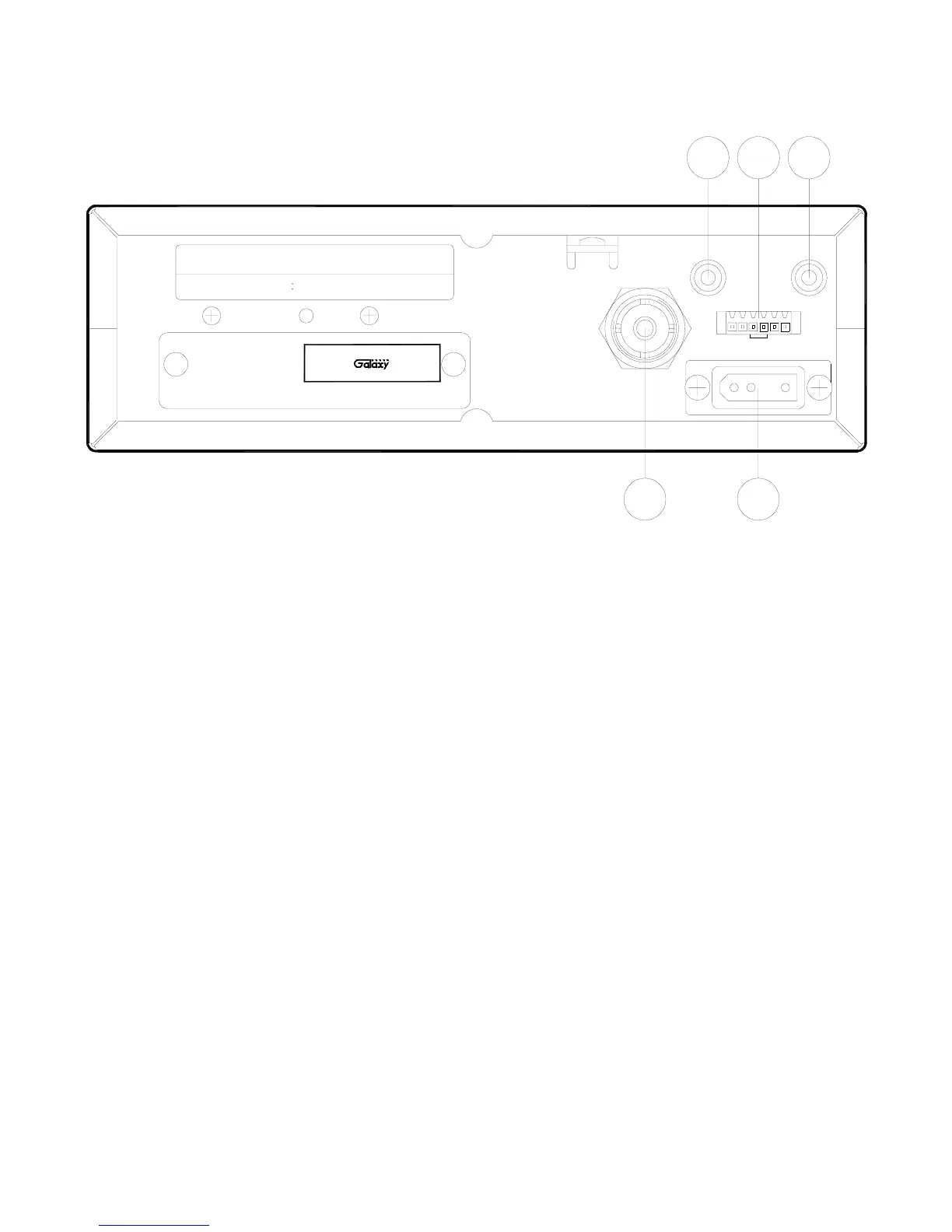
Figure 2-2 represents the location of the following connections:
Figure 2-2 Rear Panel
1. ANTENNA: This jack accepts a 50-ohm coaxial cable with a PL-259 type plug.
2. DC POWER: This jack accepts the 13.8V DC power cable with built-in fuse. The power cord
provided with the radio has a black and red wire. The black goes to negative and red goes to
positive.
3. PA SP.: This jack is for PA operation. Before operating, you must first connect a PA speaker (8
ohms, 4W) to this jack.
4. EXT SP.: This jack accepts a 4 to 8 ohm, 5-watt external speaker. When the external speaker is
connected to this jack, the built-in speaker will be disabled.
5. F.C.: This jack is used to connect the optional Galaxy FC347 six-digit frequency counter. All
connections, including DC power, are provided to the FC347 through this jack.
SERIAL NO. :
FCC ID : MEE − DX − 929
DATE OF MFG.:
AM 40 CH
CB TRANSCEIVER
MODEL NO. : DX 929
- DC 13.8V +
PA SP.
ANT
F.C.
EXT SP.
1 2
43 5
This device complies with part 15 of the FCC Rules. Operation is subject
to the condition that this device does not cause harmful interference.
Service Manual at www.GalaxyRadios.com
 Loading...