10. To bend more conduit of the same material and at the
same angle, load and secure as described in steps 3
through 6. To bend the same type conduit but at a different
angle, load and secure; turn angle set knob to the desired
angle, then press the bend button.
11. Bending different type and size conduit requires repeating
steps 2 through 10.
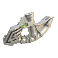
4.3 Offset Bending
1. Obtain distance “M” from table A, and measure this
distance from mark #1 and place mark #2.
2. Now place mark #1 in line with front edge of shoe clamp
and make first bend.
3. Next rotate conduit 180° level, place mark #2 in line with
front edge of shoe clamp and make second bend.
NOTE: When bending rigid aluminum, set bend angle indicator
approximately 4° short of desired angle, since aluminum does
not have spring-back of steel.
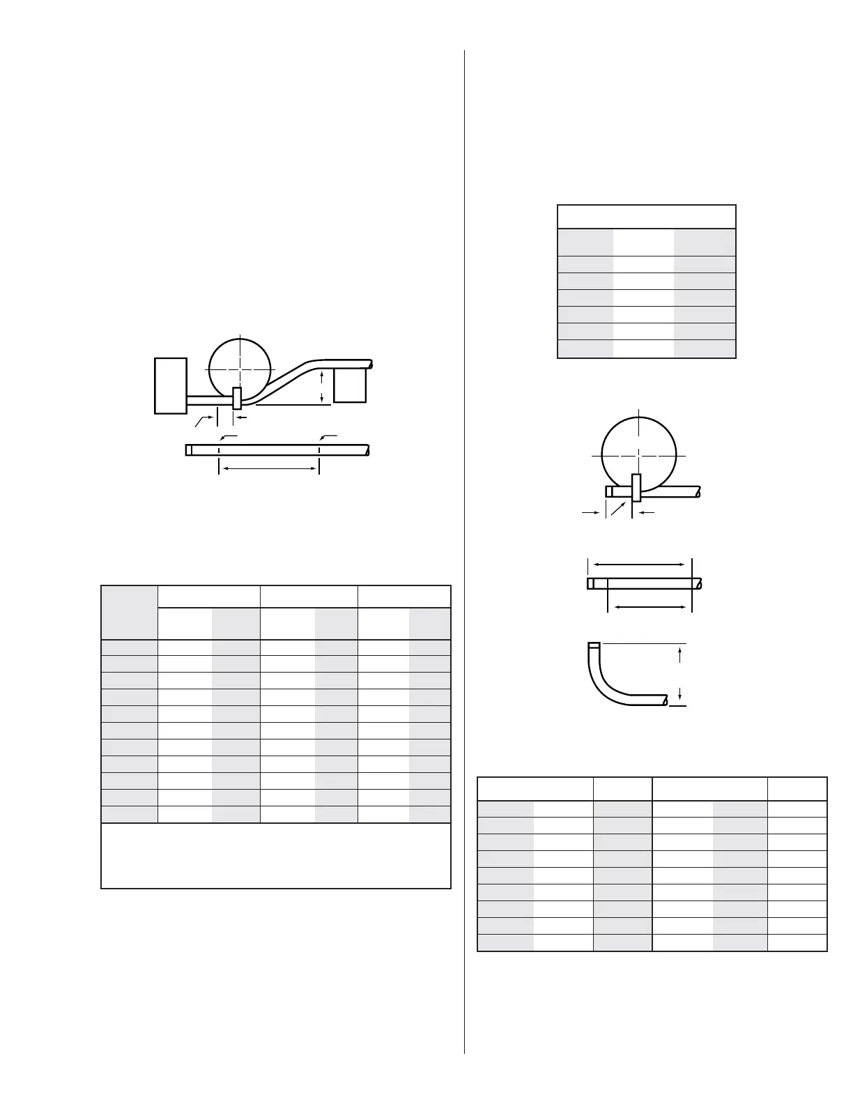
4.4 Stub-up Bending
1. Table C shows minimum length (inches).
2. Mark #1 is stub length, deduct from this as per table C
and obtain mark #2.
Min. 2"
5
Offset Conduit Conduit Conduit
Required Max. Size M Max. Size M Max. Size M
2"
3
⁄4"7
3
⁄4"
4" 1
1
⁄2"15
7
⁄16"
3
⁄4"8"
6" 2" 23
3
⁄16" 1" 12"
1
⁄2"8
1
⁄2"
8" 30
5
⁄8"1
1
⁄2" 16" 1" 11
5
⁄16"
10" 38
5
⁄8" 2" 20" 1
1
⁄4"14
1
⁄8"
12" 46
3
⁄8" 24" 1
1
⁄2"16
15
⁄16"
14" 54
1
⁄16" 28" 2" 19
13
⁄16"
16" 61
13
⁄16" 32" 22
5
⁄8"
18" 67
7
⁄16" 36" 25
7
⁄16"
20" 77
1
⁄4" 40" 28
1
⁄4"
22" 85" 44" 31
1
⁄8"
To locate distance between centers of offset bending marks other than listed in
table A use the following multipliers:
15° bend - 3.9
30° bend - 2.0
45° bend - 1.4
Table A
15° Bend 30° Bend 45° Bend
 Loading...