Do you have a question about the Gardner Denver L07 and is the answer not in the manual?
Provides notes regarding the compressor's design, quality, and environmental compliance.
Details the machine's intended purpose and risks of misuse by unqualified personnel.
Emphasizes the importance of periodic maintenance for reliable operation and availability of services.
Introduces the operating instructions and their purpose in safe and cost-effective operation.
Explains hazard symbols and liability for non-compliance with safety instructions.
Covers organizational measures, personnel responsibilities, and general precautions for safe operation.
Prohibits unauthorized changes to the machine that could affect safety.
Details safety aspects for installation, lifting, and general operation procedures.
Outlines safety precautions for maintenance, repair, and special operations.
Highlights specific hazards like electric energy, hydraulics, pneumatics, and noise.
Provides guidelines for storing compressors to prevent corrosion and protect components.
Explains various warning symbols used throughout the manual for safety communication.
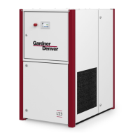
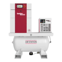
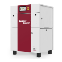
Describes the overall design and components of the L07-L11 (RS) screw compressor unit.
Presents a schematic diagram illustrating the internal workings and connections of the compressor.
Details the flow and function of the oil circulation system within the compressor.
Explains the path and process of intake air through the compressor and into the consumer network.
Introduces the control system governing the compressor's operation, including specific models.
Provides instructions on how to open and close the detachable plastic hood for access.
Outlines safe procedures and precautions for transporting the compressor unit.
Details the safety requirements and considerations for installing the compressor unit.
Specifies the required cooling air volume and minimum duct cross-section for proper heat dissipation.
Guides on connecting the compressed air line system to the compressor unit.
Provides recommended cable cross-sections and fuse sizes for electrical connections.
Instructs on removing transport fasteners from the electric motor before commissioning.
Details the procedure for checking the oil level in the pressure reservoir.
Lists the sound pressure levels for different compressor models.
Outlines the step-by-step procedure for the initial commissioning of the compressor.
Describes the steps for routine commissioning after maintenance or restarts.
Provides instructions on how to safely restart the compressor after a malfunction shutdown.
Introduces the control system and its basic operation for commissioning.
Explains the function of the different keys on the control panel for navigation and operation.
Describes the three-row display and light signals for status, faults, and warnings.
Guides on navigating sub-menus to display and change operational values.
Covers setting default parameters like language, network pressure, and timers.
Details the procedure for safely starting the compressor unit.
Explains the normal procedure for switching off the compressor unit.
Describes the function and usage of the emergency off button.
Guides on how to acknowledge and clear warning and fault messages.
Illustrates the menu structure for specific compressor models.
Illustrates the menu structure for L07RS-L11RS compressor models.
Emphasizes the importance of timely maintenance for optimal performance and satisfaction.
Refers to motor operating instructions for maintenance of the electric motor.
Outlines safety precautions and points to observe before performing maintenance.
Provides detailed instructions for changing the oil in the compressor unit.
Details the procedure for replacing the oil filter cartridge.
Explains how to change the fine separator cartridge.
Guides on checking and replacing the air intake filter.
Describes how to test the safety valve and the danger of operating with a defective one.
Provides instructions for changing V-belts and highlights automatic tensioning system.
Covers checking and re-tightening terminals and setting the control transformer.
Advises checking and re-tightening fittings in air and oil circuits.
Outlines general cleaning procedures for the compressor unit and its components.
Details the process for cleaning or changing cooling air filter mats and control cabinet filters.
Specifies inspection intervals for pressure vessels and electrical installations.
Offers recommendations for lubricants and their impact on service life.
Lists possible causes and remedies for the unit failing to start.
Identifies causes for the unit stopping during the start-up phase and their solutions.
Addresses issues where the unit fails to achieve the set mains pressure.
Provides solutions for common causes of the unit switching off unexpectedly.
Explains causes and remedies for excessive idling pressure.
Discusses reasons for oil in the compressed air and their solutions.
Covers causes of oil in the air filter and how to resolve them.
Explains why the safety valve might open and how to address it.
Presents detailed technical specifications for the L07-L11 60 Hz models.
Lists detailed technical specifications for the L07RS model.
Provides detailed technical specifications for the L11RS model.
Shows layout plans and dimensions for the L07-L11 and L07RS-L11RS models.
| Model | L07 |
|---|---|
| Power | 7.5 kW |
| Voltage | 400 V |
| Motor power | 7.5 kW |
| Type | Rotary Screw Compressor |
| Max Pressure | 8 bar |
| Pressure | 8 bar |
| Phase | 3 |