Do you have a question about the Gared PSS ADJUST-A-GOAL and is the answer not in the manual?
Do not climb on the goal, backboard, or backstop. Unit is designed for specific operating weight.
Keep hands, arms, and body clear during operation.
Ensure 5/8" mast clamp U-bolt nuts are torqued to 94-130 Ft-Lbs [128-176 Nm] for safety.
Install stop bolts on each side of the mast clamp after final adjustment to prevent backboard slippage.
Lists necessary tools and provides a recommended bolt torque chart for secure assembly.
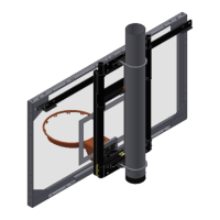
Describes the basic 1131 unit and instructions for models 1171/1171-220 with electric adjusters.
Instructions for attaching the DME to the height adjuster frame using supplied bolts.
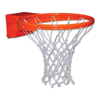
Guidance on attaching the backboard and goal to the DME, leaving bolts slightly loose.
Details on attaching adjustable feet to the rear of the backboard using carriage bolts or hex bolts.
Instructions for attaching the narrow board support angle (504151667) for 35" configurations.
Instructions for attaching the wide board support angle (504151666) for 63" configurations.
Illustrates mounting for specific board models using adjustable feet and support angles.
Illustrates mounting for specific board models 1354B and 1342B using adjustable feet.
Instructions for final tightening, leveling the board and goal to 10' height.
Guidance on applying the height and arrow decals for accurate height indication.
Detailed steps for installing the height adjuster onto a single post mast using U-bolts and stop bolts.
Crucial safety warnings regarding U-bolt torque and stop bolt installation for single post mounting.
Instructions for attaching the height adjuster to wall mount frames using 1/2" nuts and bolts.
Details on attaching the Adder Bracket for 48" high backboards, requiring drilling for 3/8" bolts.
Guidance on mounting the height adjuster to dual post systems using U-bolts on horizontal cross pipes.
Provides wiring schematics for 115V and 230V systems, including circuit requirements and motor specs.
Instructions for using the crank to lift or lower the manual height adjuster between 10' and 8'.
Guide for operating the electric adjuster via key switch, including limit switch function and instant reverse.
Details on lubricating main slide tubes and the rod assembly every 6-8 months using White Lithium grease.
| Material | Steel |
|---|---|
| Adjustable Height | Yes |
| Height Range | 7.5' to 10' |
| Base Width | 48" |
| Portable | Yes |
| Adjustment Range | 7.5' to 10' |