Parte # 4523104 Rev 3 (03/04/10)Página 34
DIMENSIONES Y ESPECIFICACIONES
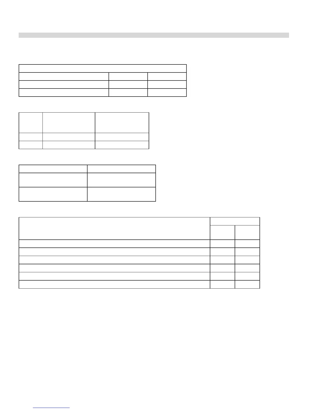
Separaciones
Las Separaciones Aplican A Todos Los Modelos
Supercie Lados Parte Posterior
Mínimo A Una Pared Combustible 14” (356mm) 6” (152mm)
Mínimo A Una Pared No Combustible 0” 0”
Presiones De Gas
Gas
Presión De
Suministro Mínima
Presión De
Operación En El Tubo
Distribuidor
Natural 7” CDA (17.5 mbar) 4.5” CDA (11.25 mbar)
Propano 11” CDA (28 mbar) 10” CDA (25 mbar)
Gas Inlet Size
Anchura Del Modelo Conexión
24” (610mm) &
36” (914mm)
3/4” NPT
Conexión De Gas Trasera
48” (1219mm) &
60” (1524mm)
1” NPT
Conexión De Gas Trasera
Caudal De Entrada A Los Quemadores Individuales
Quemador
Caudal BTU/HORA
Gas
Natural
Gas
propano
Hornillas 33,000 26,000
Quemador De Plancha De Calor Uniforme (“Hot Top”) (En Lugar De 2 Hornillas) 18,000 18,000
Quemador De Plancha De Asar (En Lugar De 2 Hornillas) 18,000 18,000
Parrilla De Plancha Levantada (Consiste En 3 Quemadores) 33,000 33,000
Quemador De Horno Para Horno Convencional O De Convección De Tamaño Completo 38,000 32,000
Horno Ahorrador De Espacio 32,000 28,000
Los caudales son para instalaciones a alturas de hasta 2000 pies (610 m) por encima del nivel del mar
 Loading...