190-00709-05 Rev. D
Garmin G1000 Pilot’s Guide for the Socata TBM 850/900
409
HAZARD AVOIDANCE
PRACTICAL APPLICATION USING THE BASIC TILT SETUP
With the antenna tilt set as previously described, any displayed target return should be scrutinized when
flying at altitudes between 2,000 and 30,000 feet AGL. If the displayed target advances on the screen to
within 5 nautical miles of the aircraft, avoid it. This may be either weather or ground returns that are 2,000
feet or less below the aircraft. Raising the antenna tilt 4 degrees can help separate ground returns from
weather returns in relatively flat terrain. This aligns the bottom of the radar beam parallel with the ground.
Return the antenna tilt to the previous setting after a few sweeps.
If the aircraft is above 29,000 feet, be cautious of any target return that gets to within 30 nautical miles.
This is likely a thunderstorm that has a top high enough that the aircraft cannot fly over it safely.
If the aircraft altitude is 15,000 feet or lower, setting the displayed range to 60 miles may be more helpful.
Closely monitor anything that enters the display.
Also, after setting up the antenna tilt angle as described previously, ground returns can be monitored for
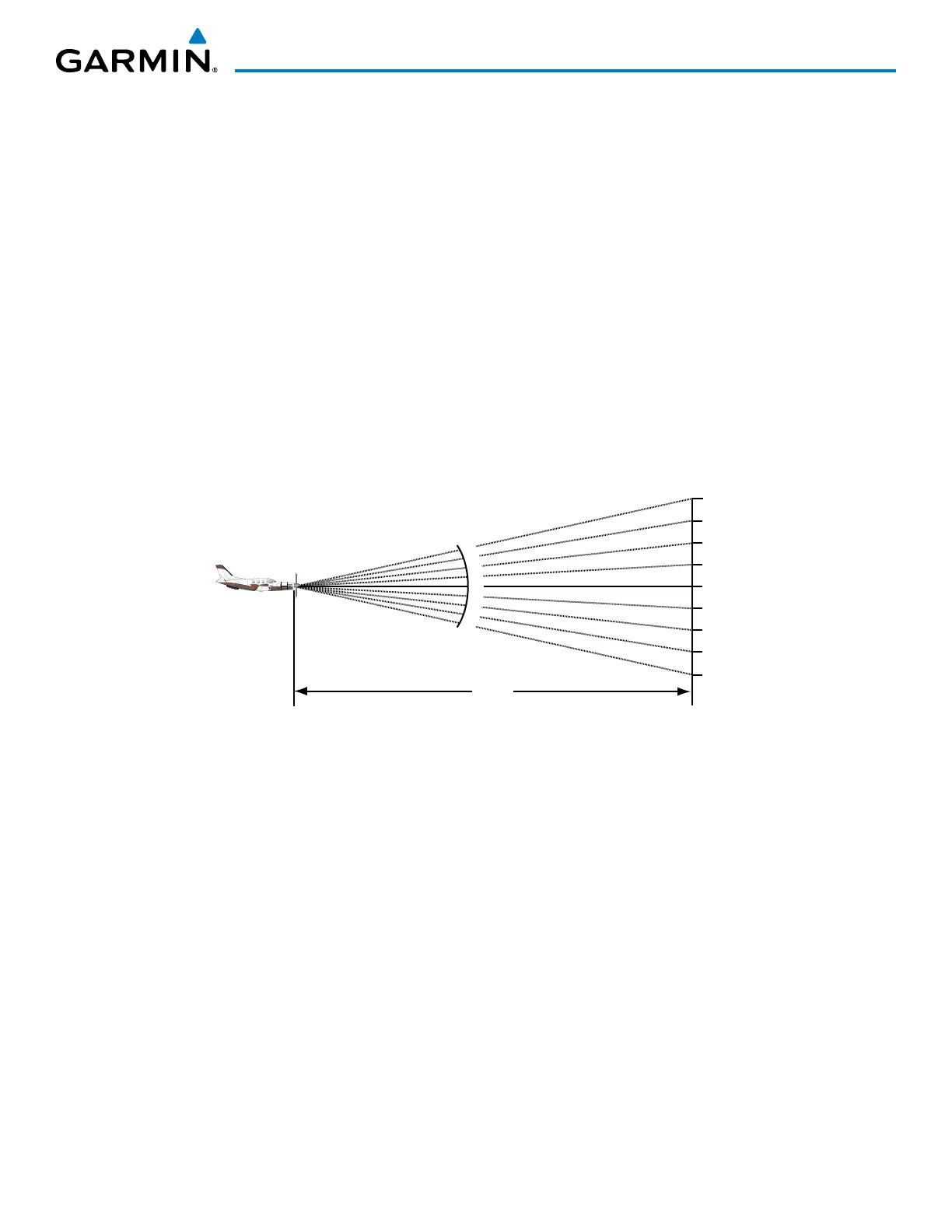
possible threats. The relationship between antenna tilt angle, altitude, and distance is one degree of tilt equals
100 feet of altitude for every one nautical mile.
Vertical Change of Radar Beam (feet)
Change in Antenna Tilt
10 nm
0
1000
2000
3000
4000
1000
2000
3000
4000
-1°
0°
-2°
-3°
-4°
+1°
+2°
+3°
+4°
Figure 6-101 Vertical Change in Radar Beam per Nautical Mile
Therefore, with the antenna tilt set so that the bottom of the beam is four degrees below parallel with
the ground, a target return at 10 nm is approximately 4,000 feet below the aircraft; at 20 nm, 8,000 feet;
at 50 nm, 20,000 feet. In other words, at this tilt setting, a ground return (such as a mountain peak) being
displayed at 10 nm would have a maximum distance below the aircraft of 4,000 feet. When that ground
target return moves to 5 nm, the maximum distance below the aircraft is 2,000 feet.
This setup provides a good starting point for practical use of the weather radar. There are many other
factors to consider in order to become proficient at using weather radar in all situations.

 Loading...


