Page 4-34 G1000 / GFC 700 System Maintenance Manual - 300/B300 Series King Air
Revision 4 190-00716-01
5) Monitor and plot voltage values at 10-minute intervals.
6) Note voltage on Digital Voltmeter at 48.0 minutes (PS-835D) or at 20.0 minutes (PS-835C).
This voltage must be greater than 20.0 Vdc.
a. All INDIVIDUAL CELL MONITOR LED’s (Figure 4-5, Item 1) must remain on.
b. Any LED that does go OFF will represent a defective individual cell, which must be replaced.
7) Remove the Load Resistor from J1 connector pins 11 (+) and 7 (-).
8) Position all INDIVIDUAL CELL DIP SWITCHES (Figure 4-5, Item 5) to the OFF position.
9) Compare the voltage vs. time plot created during this test to that of curve identified as typical for the
External Load test method on the chart above. If the plot reveals a discharge curve that meets or
exceeds the MINIMUM ACCEPTABLE DISCHARGE CURVE, the unit is considered satisfactory.
10) If unit discharge plot is satisfactory and no other failures were revealed, perform the Charging
Procedure within 2 hours of completion of the discharge test. Return the unit into service.
4.16.3 Cell Isolation Test
NOTE
No power should be applied to PS-835 Emergency Power Supply during test. This test is
performed with the battery removed from the aircraft.
A. Press and hold TEST SWITCH (Figure 4-5, Item 4). If no OUTPUT VOLTAGE MONITOR LED's
come on:
1) Position all INDIVIDUAL CELL DIP SWITCHES (Figure 4-5, Item 5) to the ON position.
2) Press and hold TEST SWITCH (Figure 4-5, Item 4) and observe the INDIVIDUAL CELL
MONITOR LED's (Figure 4-5, Item 1).
a. If all INDIVIDUAL CELL MONITOR LED’s come on except DS12, the unit is damaged
and requires repair at an authorized repair station.
b. If all INDIVIDUAL CELL MONITOR LED’s are on, a low-battery voltage condition exists.
B. Perform the Charging Procedure.
4.16.4 Charging Procedure
(Constant-Voltage Charging Method)
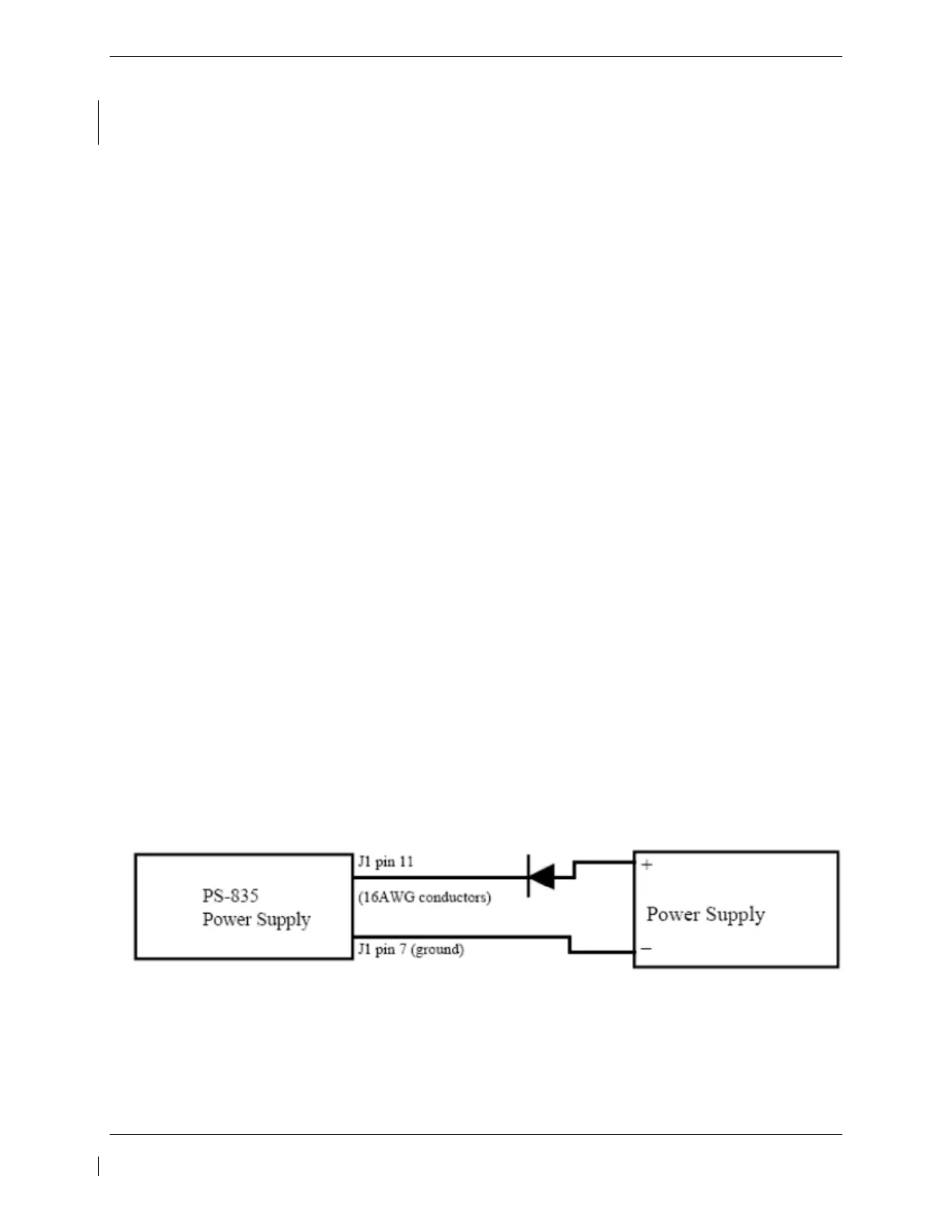
Locally manufacture a power cable using 16AWG wire and the appropriate mating connector. Include a
Diode (15 Adc (min), 50.0 PIV or greater) to prevent battery discharge in case of loss of power from the
power source. Using the external power supply apply 30.0 Vdc (10A maximum current limited) to J1
connector pins 11 (+) and 7 (-) and charge the unit for 16 hours. The batteries should reach 80% capacity
within 1 hour and full charge at 16 hours.
Figure 4-6, Power Supply Connection

 Loading...


