DELAY MODE - CAL MODE - UNITY GAIN MODE
One-minute delay modes, during which the 4-20mA
signal is locked at 4mA to prevent erroneous alarm
trips, are invoked after power-up and upon exiting
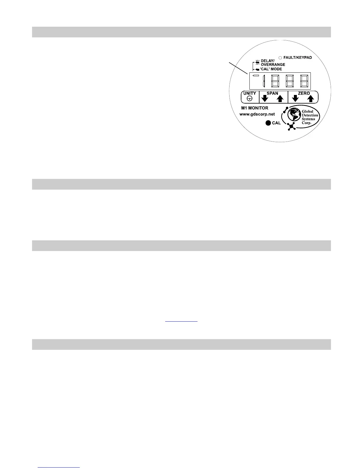
the CAL-MODE. Delay mode is indicated by a
slow flashing of the left arrow. CAL-MODE is
invoked by briefly holding the magnet tool over the
CAL key until CAL appears on the LCD. From
CAL-MODE, UNITY GAIN mode is invoked by
briefly holding the magnet over the UNITY key.
UNITY simply means the magnetic controls are
applying no gain and no offset (offset = 0, gain =
1). This allows viewing of the unconditioned signal
from the I/O board’s bridge circuit on the LCD.
However, remember negative readings may only
be viewed in CAL-MODE. At all other times the M1
suppresses negative readings to 0 until –10% is
exceeded causing a FAULT indication.
Left Arrow Indicator
Steady = Cal Mode,
Slow flash = Delay,
Fast flash = Overrange
GDS Corp.
2513 Hwy 646
Santa Fe, Texas 77510
(409) 927-2980 (409) 927-4180 fax
www.gdscorp.com info@gdscorp.com
ROUTINE CALIBRATIONS (After Initial Setup)
Hold the magnetic wand to the CAL key until CAL appears on the LCD. With ZERO gas applied to the sensor,
use the UP/DOWN ZERO keys to zero the LCD reading. Apply a known SPAN gas (typically 50% LEL) and use
the UP/DOWN SPAN keys to obtain the correct gas value reading on the LCD. Hold the wand to the CAL key
again to exit the CAL-MODE.
REASONS TO READ THE ENTIRE M1 MANUAL
Learn to use the “4-20mA Source Mode” feature in section 3.8.
Learn to use the “End of Sensor Life” (ESL) feature in section 3.9.
Learn to replace sensors without throwing away the stainless steel sensor head in section 4.4.
Learn to view new offset and gain settings after calibrations in section 3.3.1.
Learn to configure the LCD full scale reading for other ranges in section 3.7.
Learn about the flashing LCD over-range indication in section 3.2.
Please see ISA publication RP12.13 Part II-1987 (www.isa.org
) for additional information concerning
recommended operating procedures for these detectors.
SPARE PARTS AND ACCESSORIES
10-0198 Sensor splash guard with remote calibration port
10-0203 Sensor calibration cup
10-0205 Sensor flow cell for process monitoring
10-0187 Sensor replacement tool kit
1000-0076 Small magnetic wand for NEMA enclosures
 Loading...