Do you have a question about the GE MDS MDS SD4 Series and is the answer not in the manual?
Details RF exposure guidelines and recommended safety distances for the MDS SD4 radio based on antenna gain.
Explains FCC Part 15 rules, including conditions for operation and potential voiding of user authority.
Covers CSA/US approval for hazardous locations, outlining necessary mounting and wiring conditions for safe operation.
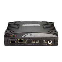
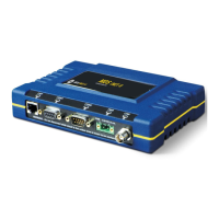
Describes the interface connectors and indicators located on the front panel of the MDS SD4 transceiver.
Lists available accessories for the transceiver and notes that shipment contents may vary based on customer requirements.
Provides instructions for mounting the transceiver to a stable surface using provided brackets and screws, with a caution about screw length.
Guides on installing the antenna and feedline, emphasizing aiming directional antennas and using low-loss coaxial feedline.
Details connecting data equipment to COM2 and primary power to the transceiver, specifying voltage and current requirements.
Outlines steps for initial radio configuration via a PC connection, including setting frequencies and modem parameters.
Explains the function of LED status indicators on the transceiver's top panel and Ethernet/LAN connector.
Describes event codes for alarm conditions, how to check alarms using STAT command, and definitions of Major/Minor alarms.
Details the built-in spectrum analyzer tool for diagnosing interference problems on or near the operating channel.
Explains how to connect a PC to COM1 for diagnostics and external devices to COM2, including wiring and data rate details.
Provides a summary of technical specifications including general, transmitter, receiver, data, power, environmental, and diagnostics interface details.
| Operating Temperature | -40°C to +70°C |
|---|---|
| Interface | Ethernet, Serial |
| Power Output | 1W (30 dBm) |
| Modulation | FHSS |
| Security | AES Encryption |
| Power Supply | +10 to +30 VDC |
| Sensitivity | -110 dBm |