Do you have a question about the GE Measurement Sentinel LCT4 and is the answer not in the manual?
Explains different types of informational notes and safety warnings.
Highlights general safety responsibilities and area considerations.
Discusses safety standards for operating auxiliary equipment.
Provides a general introduction to the flow meter.
Details the intended uses and industries for the meter.
Lists the key benefits and unique features of the Sentinel LCT4.
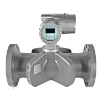
Describes the physical parts that make up the Sentinel LCT4 system.
Explains the information found on the system's tag plates.
Explains the underlying ultrasonic transit-time measurement principle.
Details how the transit time technique works for flow measurement.
Describes the function and replaceability of the ultrasonic transducers.
Explains the use of multiple measurement paths for accuracy.
Discusses the impact of flow profile on ultrasonic measurement accuracy.
Provides tables for flow rate ranges based on pipe size.
Lists detailed technical specifications for the system.
Details performance metrics like linearity, accuracy, and stability.
Covers meter body materials, flowcells, and flange ratings.
Describes the electronic components, weight, dimensions, and inputs/outputs.
Lists approvals relevant for custody transfer applications.
Lists the standards the Sentinel LCT4 is designed in accordance with.
Specifies operational limits for temperature and pressure.
Details the temperature ranges for operation and storage.
Lists maximum operating pressures based on material and flange class.
Provides dry weight specifications for the assembled unit.
Lists OIML approved minimum and maximum flow rates.
Specifies the types of fluids the meter is suitable for.
Details various certifications like PED and CRN.
Information regarding the PED certification.
Provides the CRN details for Canadian registration.
Lists approvals specific to custody transfer performance.
Lists relevant drawings and documentation for system installation and maintenance.
Lists available wiring diagrams for the electronics.
Lists available outline and installation diagrams.
Standard warranty and legal disclaimer.
Important safety warnings and precautions for operation.
General guidelines for safe and reliable system installation.
Lists the items included in the shipment.
Instructions for safely removing the system from its packaging.
Procedures for inspecting components prior to installation.
Covers the physical mounting and placement of the meter.
Details requirements for selecting the installation location and straight pipe runs.
Important considerations before and during installation.
Safe methods for lifting and handling the meter.
Step-by-step guide for physically installing the meter.
Recommendations for piping installation to ensure performance.
Specifics on choosing the installation site and straight pipe runs.
Defines required upstream and downstream straight pipe lengths.
Instructions for connecting power and signal wiring.
Steps for accessing the terminal boards by removing covers.
Detailed instructions for connecting the power supply.
Guidance for connecting serial communication ports (RS232/RS485).
Instructions for connecting optional analog inputs.
Detailed instructions for wiring the analog output.
Introduction to the programming features of the instrument.
Overview of the keypad and its functions.
Explains the meaning of the various indicator lights.
Outlines the different menu categories for programming.
Allows configuration for individual physical channels.
For configuring composite channels and API corrections.
Details how to manage security levels and access.
Steps to unlock the display and user program.
Options for managing security settings like passcodes and timeouts.
Allows modification of user and administrator passcodes.
Configuration steps for individual channels.
How to enable or disable measurement channels.
Setting parameters affecting the transducer signal, like Zero Cutoff.
Configuring limits for signals to detect errors.
Programming for composite measurements and advanced features.
Selecting or defining fluid properties for accurate measurement.
System-wide configuration settings like units, communication, and totals.
Configuration of analog outputs, frequency/totals, alarms, and slots.
Programming the 4-20 mA analog output signal.
Configuring frequency and totalizer outputs.
Setting up alarm conditions and their behavior.
Customizing display settings like contrast and backlight.
Procedure for calibrating the 4-20 mA analog output loop.
Managing user access levels and passcodes.
Changing passcodes for different user levels.
Accessing and managing factory settings and information.
Overview of MODBUS/RTU protocol support.
Step-by-step guide to configure MODBUS parameters.
Overview of HART communication capabilities.
Diagrams for connecting a HART communication device.
Procedures for setting up HART communication via software or keypad.
Details on how the meter interacts with other devices.
Describes sensor input and actuator output channels.
Lists and explains the device variables available via HART.
Procedures for calibrating outputs and inputs.
Step-by-step guide to update the meter's firmware.
How to verify the installed software and option card versions.
Detailed procedure for trimming the analog output loop.
Guidelines for inspecting and maintaining the physical components.
Instructions for maintenance of the pipe flange connections.
Procedures for servicing sensor ports and the transmitter interface.
Information on ordering and replacing spare parts.
Guidance on how to properly install replacement components.
Introduction to troubleshooting the Sentinel LCT4.
Lists and explains all error codes, their causes, and actions.
Indicates no error condition is present.
Addresses issues with poor ultrasonic signal strength.
Deals with soundspeed exceeding programmed limits.
Handles velocity readings outside the set limits.
Addresses issues with signal quality falling outside limits.
Deals with signal amplitude exceeding programmed limits.
Handles acceleration errors often caused by erratic flow.
Addresses issues with the analog output signal being outside limits.
How to view diagnostic parameters for troubleshooting.
Troubleshooting issues related to the fluid and the installation pipe.
Discusses how fluid properties can affect measurement accuracy.
Troubleshooting issues related to transducers.
Information on how the system logs events and changes.
Details what activities are recorded in the audit log.
How to retrieve and view audit log data.
Discusses factors affecting flow rate uncertainty.
Lists the available menu flow diagrams in the appendix.
Introduction to CE Mark and EMC/LVD directives.
Wiring modifications required for EMC compliance.
Explains the purpose of the service record.
Instructions for recording service data.
| Brand | GE Measurement |
|---|---|
| Model | Sentinel LCT4 |
| Category | Measuring Instruments |
| Language | English |