Cables
GFK-0356Q Chapter 10 Cables 10-19
10
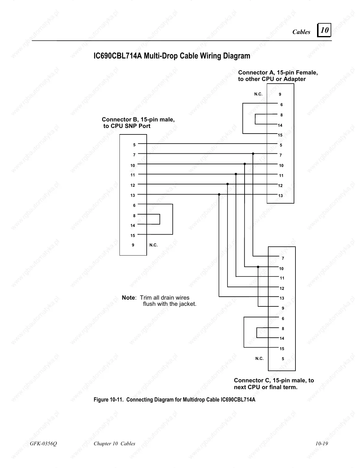
IC690CBL714A Multi-Drop Cable Wiring Diagram
5
7
10
11
12
13
6
8
14
15
6
8
14
15
5
7
10
11
12
13
9
7
10
11
12
13
6
8
14
15
9
N.C.
5
N.C.
Connector B, 15-pin male,
to CPU SNP Port
Connector A, 15-pin Female,
to other CPU or Adapter
Connector C, 15-pin male, to
next CPU or final term.
9
N.C.
Note: Trim all drain wires
flush with the jacket.
Figure 10-11. Connecting Diagram for Multidrop Cable IC690CBL714A

 Loading...


