EasyManuals Logo

GE AF-600 FP Series Design And Installation Guide

GE AF-600 FP Series
121 pages
To Next Page IconTo Next Page
To Previous Page IconTo Previous Page
Page #16 background imageLoading...
Page #16 background image
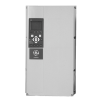
Illustration 2.1 Top and Bottom Cooling Clearance
Size 12-15 21-24 31, 33
32, 34, 41h, 42h, 43h,
44h, 51, and 52
a/b [mm] 100 200 200 225
Table 2.1 Minimum Airflow Clearance Requirements
Installation
AF-600 FP
TM
Design and Installation Guide
DET-768b 13
2
2

Table of Contents

Other manuals for GE AF-600 FP Series

Questions and Answers:

Question and Answer IconNeed help?

Do you have a question about the GE AF-600 FP Series and is the answer not in the manual?

GE AF-600 FP Series Specifications

General IconGeneral
BrandGE
ModelAF-600 FP Series
CategoryI/O Systems
LanguageEnglish

Related product manuals