Revision C 170 Series Monitor 5-23
2000947-004
Theory of Operation: Main Board Theory of Operation
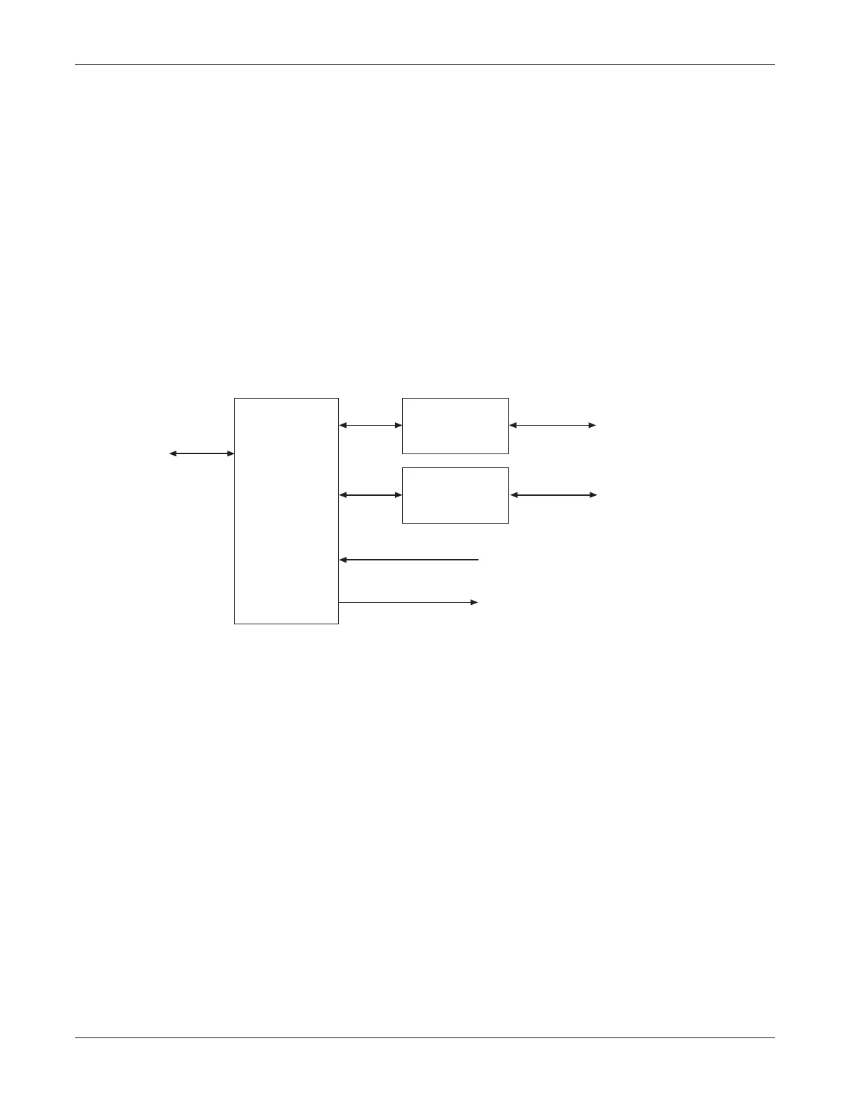
Communications Module
The communications section consists of quad UART U21 and RS-232 transceivers
U19 and U20. The baud rate frequencies are generated from crystal X3 (3.6864
MHz). Two of the RS-232 channels are used for external communications while the
remaining two provide spare internal channels. Each channel has four ports for
RTS/CTS/general input-output. Both external channels support the RTS/CTS lines.
Transceivers U19 and U20 convert the UART 3 V digital communications lines to
RS-232 levels (±7 V typically) for transmission; and ±7 V RS-232 levels to 3 V
levels for reception. RJ-45 connectors J7 and J8 provide center connection
compatibility to the 6-pin RJ-11 connectors found on the 120 Series Maternal/Fetal
Monitors. The 170 Series uses the larger 8-pin connectors to provide fused power
for future interfacing. Each channel has shunt 1000 pF shunt capacitors for
emissions, 100 Ω series resistors, and clamp devices D6 and D7 for ESD protection.
Figure 5-15 provides a block diagram of the communications module.
Figure 5-15. Communications Module Block Diagram
QUAD UART
RS-232 Line
Transceivers
(Channel 1)
to Data Bus
RS-232 Line
Transceivers
(Channel 2)
TXD, RTS,
RXD, CTS
TXD, RTS,
RXD, CTS
to Rear Panel
to Rear Panel
Miscellaneous Inputs
Miscellaneous Outputs
 Loading...