3 K415 Issue No. 1
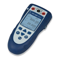
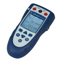
OPERATOR CONTROLS (Figure 1 and 2)
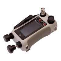
These divide into two groups, the operator/display controls (Figure 1) and the pressure/
vacuum generation components (Figure 2). The operator controls and a typical display,
common to all instrument versions, is shown below.
1 Display 2 Electrical Input Sockets 3 Electrical Output Sockets 4 Cursor
5 Enter Key 6 On/Off Key 7 Function (soft) Keys 8 Hard Keys
Figure 1 - DPI 610/615 Key-pad
Display
The display section of the instrument basically divides into four distinct sections. The two
main sections of the display are used to display a input and an output. The remaining
sections show the status display area and define the soft key functions. A typical display
is shown below:
bar
V
F2F1
COURANT
UNITES
PRESSION
FCT.: STANDARD
1
2
3
4
5
6
7
8
bar
V
COURANT
UNITES
PRESSION
FCT.: STANDARD
Affichage Measurand
(INPUT)
Affichage Source
(OUTPUT)
Cases Programmables
Ligne Etat
Status display
Input
Output display
Soft boxes
INTRODUCTION Summary of Functions
 Loading...