to the memory location map for more details.
Refer also to the ATS1290 manual for the direct link to the zone number
(control panel).
For convenience, the output also can be configured to connect to any
output in the DGP range (for more details, see the explanation at the and of
the memory location map).
13. The ATS Output (* see Memory Location Map
below)
The ATS output can be used to enable/disable the alarm LED or Walk test
LED on the detector.
The ATS output and zone numbering are equivalent.
The default output number for activating a walk test of the device equals
the input number when memory location 6 is set to 0 (default).
The default output number for activating a Day/Night status of the device
equals the input number +1 when memory location 7 is set to 0 (default).
Refer to the PID DGP manual for PID address settings and zone numbering.
The output number on the EV435AM-AD can also be changed within the
DGP output range (i.e. DGP 1 output 17-32).
If the output for a walk test, of this device or all the outputs of similar
devices on the same DGP need to be programmed on i.e. output 32, pro-
gram memory location 6 of all those I/O devices to 32.
The same programming is applicable for memory location 7 for the Day/
Night status.
The walk test and Day/Night (or arm / disarm) functionality can be pro-
grammed via event flags and output through the control panel.
14. Memory Location Map
Every addressable device has its own characteristics concerning related
I/O lines or certain functionality of the device.
A total of 16 memory locations are reserved to configure the PID devices.
Only the first 9 normally are user configurable. This depends on the func-
tionality of the particular device.
- 3 -
Memory Location map for the EV435AM-AD
Location Function Direction Value returned on READ CONFIG
[Binary values]
1 Auto Reset R/W 0000 0000 = Reset after PIR alarm (default)
0000 0001 = Authorised reset
2 AM Sensitivity R/W 0000 0000 = High sensitivity (default)
0000 0001 = Low sensitivity
3 Range R/W 0000 0000 = High sensitivity (default)
0000 0001 = Low sensitivity
4 Process Mode R/W 0000 0000 = 3D+ (default)
0000 0001 = Bi-Curtain
5 Trouble to Relay R/W 0000 0000 = Trouble / Mask alarm only to ETO (default) second zone address
0000 0001 = Trouble / Mask alarm also to alarm output (first zone address)
6 Walk Test output R/W 0000 0000 = Walk Test output number
7 Day/Night output R/W 0000 0000 = Day/Night output number
For the EV435AM-AD, only the first seven memory locations are relevant.
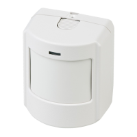
15. Technical Specifications
Specified mounting height min. 1.8 m - max. 3.0 m
Target speed range min. 0.1 m/sec - max. 4.0 m/sec
Temperature range -18 °C to +55 °C
Alarm time min. 2.5 sec.
Relative humidity max. 93%
Dimensions 103 x 71 x 53 mm
Weight 120 g
Number of zones 9
Max. detection range 16 m
IP/IK rating (with sealed cable entry) IP30 IK02
Category
PIR
Device type T1
Bus protocol Interlogix Point ID
Bus voltage 12 or 24 V
Current consumption out of bus 4.8 mA
Unit load for DGP 16
Address range 0 to 255
When disconnecting the detector from the bus, wait one minute before
reconnecting it to ensure a clean boot.
 Loading...