Installation Instructions
WHAT YOU WILL NEED (CONT.)
• A GE water supply kit (containing tubing, shutoff
_dve and fittings listed below) is available at extra
cost fl'om your dealer or fl'om Parts and Accessories,
800.626.2002.
• A cold water supply. The water l)ressme must be
between 20 and 120 p.s.i. (] A-8.I bar).
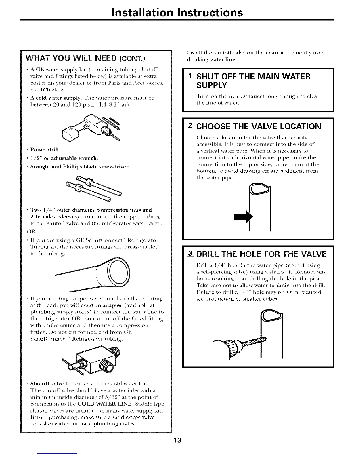
• Power drill.
• 1/2" or adjustable wrench.
• Straight and Phillips blade screwdriver.
• Two 1/4" outer diameter compression nuts and
2 ferrules (sleeves)--to connect the copper robing
to the shutoff _dve and the refrigerator water _dve.
OR
• If you are using a GE Smart(kmnec( _ Refl-_gerator
Tubing kit, the necessary fittings are preassembled
to the robing.
" If yore" existing copper water line has a flared fitting
at the end, you will need an adapter (available at
phunbing supply stores) to com_ect the water line to
the refl'igerator OR you can cut off the flared fitting
with a tube cotter and then use a compression
fitting. Do not cut _k)rmed end .4/'oIn GE
SmartConnect'" Refi'igerator robing.
• Shutoff valve to connect to the cold water line.
Tile shutoff valve should have a water inlet with a
minimum inside diameter of 5/32" at the point of
connection to the COLD WATER LINE. Saddle-t_pe
slmtoff valves are included in many water supply kits.
Before purchasing, make sure a saddle-t_pe valve
complies with your local plumbing codes.
Install the shutoff xalxe on the nearest frequently used
drinking water line.
[] SHUT OFF THE MAIN WATER
SUPPLY
Turn on tile nearest fimcet hmg enough to clear
the lille of water.
[] CHOOSE THE VALVE LOCATION
Choose a location fi>r the valve that is easily
accessible. It is best to connect into the side of
a vertical water pipe. When it is oecessarv to
coooect into a horizontal water pipe, inake the
colnlectioo to the top or side, rather than at the
bottom, to avoid drawing off aov sediu_eot fl'Oln
the water pipe.
[] DRILL THE HOLE FOR THE VALVE
Drill a l/4" hole in the "_ater pipe (e'_eo i_ using
a sell'piercing vahe) using a sharp bit. R.emoxe an)
btu'l_ resulting frou_ drilling the hole in the pipe.
Take care not to allow water to drMn into the drill.
Failure to drill a I "" ma_
/4 hole result in reduced
ice production or smaller cubes.
13
 Loading...