15
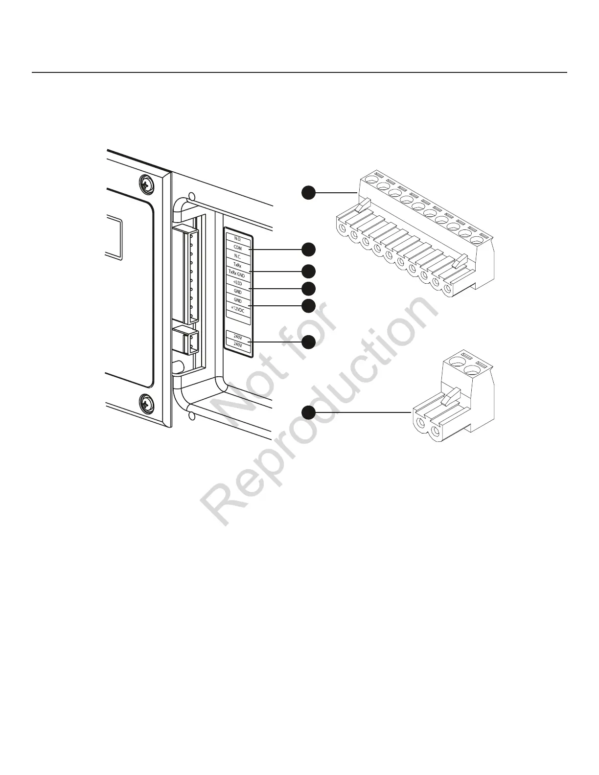
Low Voltage connections to signal fault contacts, transfer switch communication, remote LED and auxiliary 12VDC
power are made via a removable ten-pin connector plug.
Compare this illustration with your generator to familiarize yourself with the location of these connections: Count down
to the proper pin location on the control board because visual alignment with the decal can be misleading.
System Connectors
A – Ten-pin Connector Plug
B - Fault Contacts—UseNO,COMandNCtohookupa
siren, light, etc. to alert you in case of a fault. Contacts
reverse state (NO goes to NC and vice versa) upon a
fault condition.
C - Transfer Switch Communication—Connecttotransfer
switch control board for communication interface using
18AWG copper twisted pair wire.
D - Remote LED Output (Optional)—Usethistohookupthe
remote LED supplied with the generator. The remote LED
will turn on and off in a series of blinks if certain faults are
detected in the generator.
E - +12 Volt DC, .5 Amp Output—Internalauxiliary
power supply.
F - 240 Volt Utility—Usetohookupthe240Vutilityleads
from the transfer switch to the generator.
G – Two-pin Connector Plug
• For15kWpoweroutputconnection,use#6AWGminimum300volt75°C-90°Ccopperwire
• For20kWpoweroutputconnection,use#4AWGminimum300volt75°C-90°Ccopperwire
• ForUtilityCircuitconnectionuse#14AWGminimum300volt75°C-90°Ccopperwire
• Fortransferswitchcommunicationuse#18AWGtwistedpairconductors,nogreaterthan200ftinlength,300volt
75°C-90°Ccopperwire
• Whenconnectingtotheconnectorplugs,fastenonlyonewiretoeachconnectorscrew.
• Torqueconnectorplugscrewsto7in-lb(7.9Newtonmeter).
C
E
D
A
B
F
G
 Loading...


