18
System Control Panel
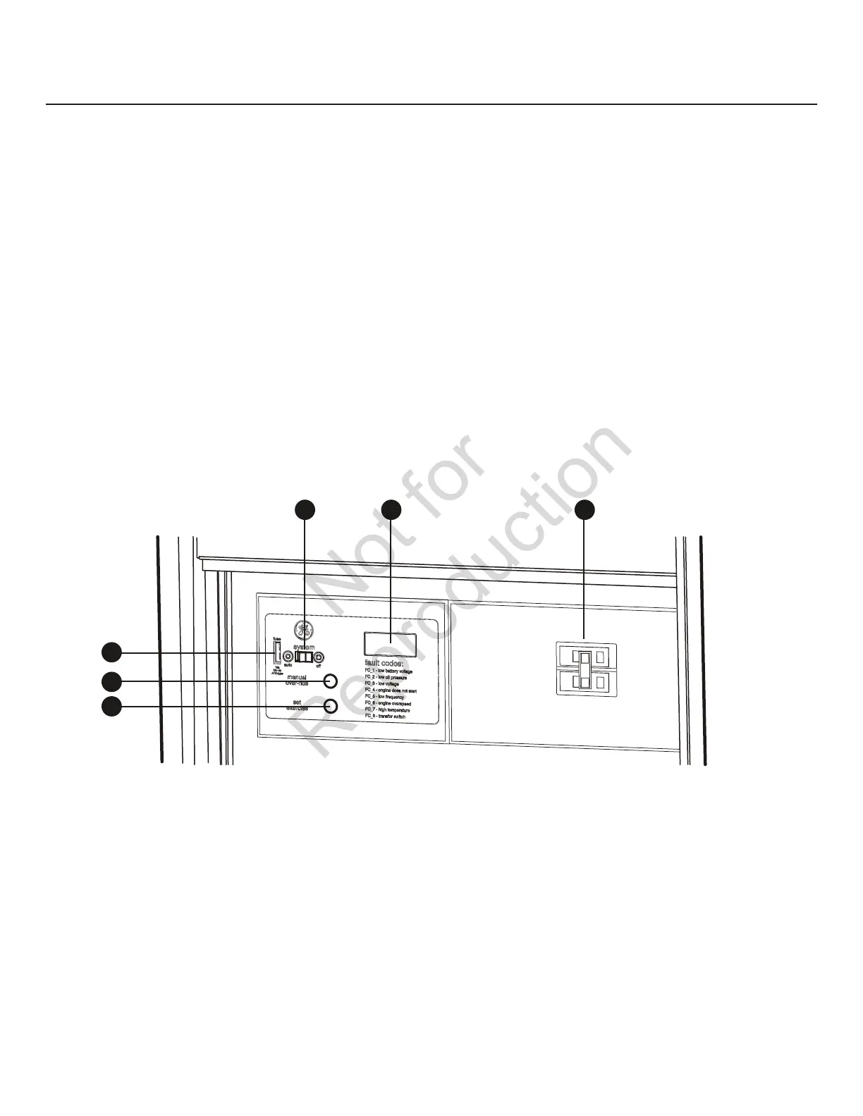
The home generator control panel, located inside the control
panel door, is shown below. Brief descriptions of the controls
used during installation are:
A - SET EXERCISE —Usedtosettheexercisecyclestarttime.
B – MANUAL OVER-RIDE—Usedtomanuallystartandstop
the generator.
C - 15 Amp Fuse—ProtectsthegeneratorDCcontrol
circuits. If the fuse has ‘blown’ (melted open) or was
removed, the engine cannot crank or start. Replace the
fuse using only an identical ATO 15A fuse. One spare fuse
is supplied with the unit. If fuse was blown or removed,
you will need to reset the exercise timer (see Setting
Exercise Timer).
D - System Switch—SwitchesmodestoOFF or AUTO.
• “AUTO”positionisthenormaloperatingposition.Ifa
utility power outage is sensed, the system will start
the generator. When utility power is restored, lets the
engine stabilize internal temperatures, shuts off the
generator, and waits for the next utility power outage.
• “OFF”positionturnsoffrunninggenerator,prevents
unit from starting and resets any detected faults.
E - Digital Display—Displaysrunningtimeinhoursor
fault codes.
F - Circuit Breaker —MustbeON to supply power to the
transfer switch.
More information may be found in Controls in the
operator’s manual.
A
D
B
E
C
F
 Loading...


