continued
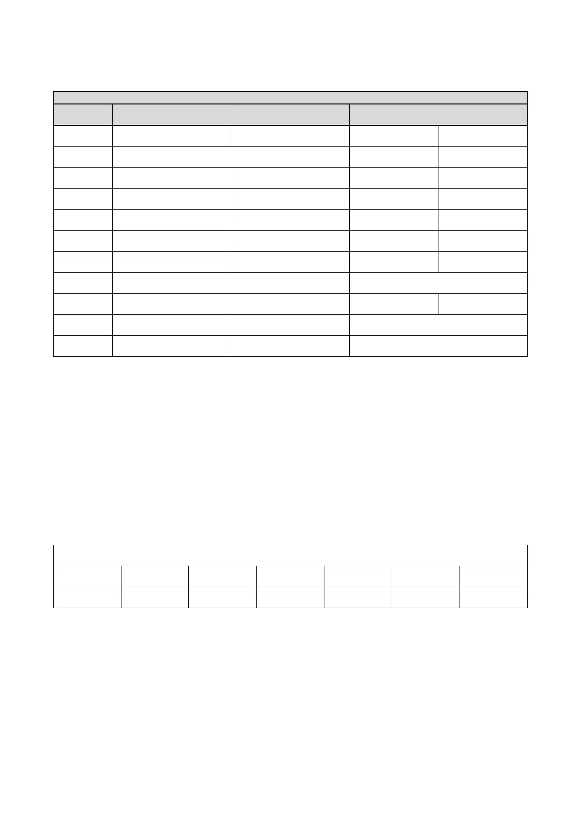
CABLE FROM TO WIRE GAUGE
hospital PDB C1 Frontal Cabinet 35 mm² AWG2
hospital PDB C1 Lateral Cabinet 35 mm² AWG1
hospital PDB C2 Cabinet 6 mm² AWG8
hospital PDB Fluoro UPS 10 mm² AWG6
hospital PDB Fluoro UPS 10 mm² AWG6
hospital PDB Frontal XRT Chiller 6 mm² AWG10
hospital PDB Ground 35 mm² mini AWG2/0 mini
hospital PDB Injector AWG10
hospital PDB Lateral XRT Chiller 6 mm² AWG10
hospital Hospital mains LDM UPS AWG12
hospital Hospital mains LDM cabinet AWG12
5.2.2 Power and Grounding Requirements
• A breaker with cut-out capability shall be installed by the customer (or his contractor) next to the PDB.
It is needed for the LOTO procedure in front of the PDB.
• The main facility ground conductor to the PDB shall be copper wire and the minimum size as required
by the local coding regulations, such as the NEC. For countries, which are not covered by local
requirement (like NEC), the ground wire to earth should be at minimum of AWG 2/0 (150 A breaker) UL
or 35mm
2
(80 A breaker) CE, or same size (100%) as feeder wires, whichever is larger.
• Power cables must not be used to supply other systems
• Cables shall be in conformity with local regulation (UL, CSA, IEC, CCC).
Table 5-5
Max Line Impedance for feeder line between Generator cabinet and Hospital
V 380 400 415 440 460 480
Ohms 0.09 0.096 0.101 0.108 0.114 0.12
NOTE
These 3 phases cables are not furnished by GE Healthcare. Provided by installer.
• These cables must be kept separated as much as possible from room system cables.
• The shield of any shielded cable coming from the distribution cannot replace the ground
wire.
Reference: For specific Vascular system grounding maps and connection details, refer to the MisMap and
mis chart listed in 5.3.1 MIS (Master Interconnect System) on page 156.
Electrical Requirements
154
Innova
TM
IGS 6
5750182-1EN 3
 Loading...