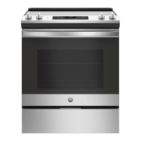
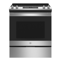
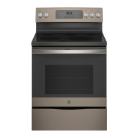
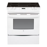
Installation Instructions
30" Electric Slide-ln Ranges
Questions? Caii 1.800.GE.CARES(1.800.432.2737) or visit www.GEApp(iances.com
In Canada, call 1.800.561.5344 or visit www.GEAppliances.ca
BEFORE YOU BEGIN
Read these instructions completely and carefully•
" I MPORTANT -- Savethese instructions
for local inspector's use.
" IMPORTANT -- Observe all governing
codes and ordinances•
o Note to Installer - Be sure to leave these
instructions with Consumer•
o Note to Consumer - Keep these instructions
for future reference.
o Skill level- Installation of this appliance
requires basic mechanical skills
and advanced electrical skills.
o Proper installation is the responsibility
of the installer.
• Product failure due to improper installation
is not covered under Warranty.
FOR YOUR SAFETY:
Tip-Over Hazard
• A child or adult can tip the range and be killed.
Install the anti-tip bracket to the wall or floor.
Engage the range to the anti-tip bracket by sliding the
range back such that the foot is engaged.
Re-engage the anti-tip bracket ifthe range is moved.
Failure to do so can result in death or serious burns
to children or adults.
you did not receive an anti-tip bracket with your purchase,
call 1.800.626.877/4to receive one at no cost. (In Canada,
call 1.800.561.3344.) Forinstallation instructions of the bracket,
visit: www.GEAppliances.com (InCanada, www.GEAppliances.ca.)
Anti-Tip Bracket
Kit Included
_WARNING Before beginning the
installation, switch power off at service
panel and lock the service disconnecting
means ta prevent power from being
switched on accidentally. When the
service disconnecting means cannot
be locked, securely fasten a prominent
warning device, such as a tag, to the
service panel.
MATERIALS YOU MAY NEED
Squeeze Connector
(ForConduit
Installations Only)
(ULListed40 AMP)
a-Wire Cord 4' long OR
3-Wire Cord 4' long
TOOLS YOU WILL NEED
Drill with 1/8" Bit Tin Snips
Safety Glasses Tape Measure
Adjustable Wrench Pliers
Level 1//4" Nut Driver
111 REMOVE PACKAGING MATERIALS:
Failure to remove packaging materials could result in damage to the appliance. Remove all packing
parts from oven, racks, heating elements and drawer. Also, remove protective film
and labels on the door, cooktop (do not remove side protection on glass cooktops)
and backguard. Do not remove protective ehannel from sides of glass eooktop, if applicable,
until later in installation.
[_] PREPARE THE OPENING (FOR INDOOR USE ONLY)
Ifthe countertop area is not flat, excesstension may be appliedto the glass cooktop causing breakage
and voidingthe warranty. Makesure the wall covering,countertop, flooring and cabinets around the range can
withstand the heat (upto 200°F)generated by the range.
A.Allow 30" minimum clearance between surface unitsand bottom of unprotected wood or metal cabinet,
or allow a 24" minimum when bottom of wood or metal cabinet is protected by no lessthen 1/4" thick flame
retardant millboard coveredwith no lessthan No.28 MSGsheet metal (.015"thick),.015"thick stainlesssteel,
.025"aluminum or .020" copper.
B.Thisappliance hasbeen approved for 0" spacingto adjacent surfaces abovethe cooktop. However,a minimum
6" spacing to surfaces lessthan 15" abovethe cooktop and adjacent cabinetry is recommendedto reduce
exposure to steam, greasesplatter and heat.Allow 1/4" minimum clearance at the back wall.
To reduce the riskof burns or firewhen reaching over hot surface elements,cabinet storagespace above the
cooktop should beavoided. Ifcabinet storage space isto be providedabovethe cooktop, the risk can
be reducedby installing a range hood that projects at least 5" beyond thefront of the cabinets. Cabinetsinstalled
abovethe cooktop must beno deeper than 13".
Front surface
of countertop
2 7/8''_-
i
/
/
i
/
/
/i
19-1/2" 20-S/8" I/
Door clearance from
front surface of "
countertop
31 i/2"-Netal Cooktops
31 i/4"-Glass Cooktops
Height from floor to range top
35 7/8"-36_1/2"
OR
36-1/2"-38" with lower trim
slide in kit (see Step 3}
NOTE:Use a 4'
power cord to prevent
interference with the
Sea note B
above.
have to be dressed Lo allow
for proper drawer closing
1/a" Hin. Flat
]1 1/8" (791 cm} D_.I
See note B above.
©
If the control panel
measures 31-1/8"
(791 ca} like in the
illustration AND ifthe
countertop has a raised
edge, shave raised edge
to clear the control panel,
as shown at left
35 7/8"-36 1/2" from
Floorto counterbp
2S"
1 1/4" Min,from counteltop
to top of cabinet drawer
29 15/16"-Z0-i/16"
Acceptable electlical
outlet area
F_ ALTERNATE INSTALLATION I CONSTRUCTION KITS
Description: Use:
Backguard Kit Adds a decorative backguard to the rear
of the range. This kit can only beused when the opening
in the eountertop is 25" deep•
Maintop Filler Kit: Adds a filler strip to the rear ofthe range. This
kit can only be used when the opening in the countertop is 25"
deep. This kit cannot be used with a backguard kit.
Maintop Filler Kit Numbers:
Designed to be used when replacing a
free-standing range with a slide-in•
Usedto fill gap between the range
back and wall.
WB07T10680 {Black)
WB07T10681 (White)
WB07T10682 (Bisque)
Body Side Kit: Contains a color-matched side panel which can Designed to be used when cabinets
be used to create a finished appearance on either side are absent on one side of the range.
of the range.
Lower Trim Kit: Contains a color-matched toe kick Usekit when countertop height is
and extra-long leveling legs. Designed to be used when 36-1/2" to 38" high.
the range needs to be raised higher than 36-1/2".
To order accessory kits, call 1•866•775•/4557, or visit www.GEAppliances.cam.
PREPARE THE RANGE
STORAGE DRAWER REMOVAL
A Pull drawer out until it stops.
B. Liftfront of drawer until the stops clear the guide•
C. Pull forward and remove the drawer•
DOOR REMOVAL {optional)
Door removal is not a requirement for installation of the product
but is an added convenience• To remove the door:
A Open the oven door as far as it will go.
B. Pushboth hinge locks down toward the door frame to the unlocked position•
This may require a fiat-blade screwdriver.
DO NOT LIFTTHE DOORBYTHE HANDLE!
Protective
Rail
aide
........
Hinge
Hin !IriS/ unlocked
s oF _pos t on
C. Place hands on both sides of the door,and close the oven door
to the removal position. (Approximately 1"-2" from the closed position•)
D. Lift door up and out until the hinge arms clear the slots•
NOTE:The oven door is very heavy. Be sure you have a firm grip before lifting the
oven door offthe hinges. Usecaution once the door isremoved•
Donot lay the door on its handle•This could cause dents or scratches•
r, ///,/
t_ '#''y
Hinge clears slot
[_] ELECTRICAL REQUIREMENTS
AWARN ING: This appliance must be properly grounded.
_, WARN I NG: All new constructions, mobile homes, recreational vehicles and installations where
local codes do not allow grounding through neutral require a 4-conductor, UL-listed range cord.
A WARN ING: To prevent fire or shock, do not use an extension cord with this appliance.
WARN ING: To prevent shock, remove house fuse or open circuit breaker before beginning
installation•
We recommend you have the electrical wiring and hookup of your range connected by a qualified
electrician. After installation, have the electrician show you how to disconnect power from the range.
You must use a single-phase, 120/208 VAC or 120/240 VAC, 60 hertz electrical system. If you connect
to aluminum wiring, properly installed connectors approved for use with aluminum wiring must be
used.
Effective January 1, 1996, the National Electrical Code requires that new construction (not existing)
utilize a 4-conductor connection to an electric range• When installing an electric range in new
construction, mobile home, recreational vehicle, or an area where local codes prohibit grounding
through the neutral conductor, refer to the section on four-conductor branch circuit connections.
Check with your local utilities for electrical codes which apply in your area. Failure to wire your oven
according to governing codes could result in a hazardous condition• If there are no local codes, your
oven must be wired and fused to meet the National Electric@ Code, NFPA No. 70 - latest edition,
available from the National Fire Protection Association•
This appliance must be supplied with proper voltage and frequency and connected to an individual,
properly grounded, 40 amp (minimum) branch circuit protected by a circuit breaker
or time-delay fuse.
Use only a 3-conductor or a/4-conductor UL-listed range cord.
These cords may be provided with ring terminals on wire and
a strain relief device•
A range cord rated at/40 amps with 125/250 minimum volt range
is required. A 50 amp range cord is not recommended, but if used,
it should be marked for use with nominal lYd' diameter connection
openings. Care should be taken to center the cable and strain relief
within the knockout hole to keep the edge from damaging the eable.
The rating plate is located on the oven frame or on the side
of the drawer frame•
Rating
plate
z _ J,,
Rating
plate
161 POWER CORD AND
CONDUIT INSTALLATION
A. Remove wire cover (on the back of range)
by removing screws using a 1/4" nut driver•
Do not discard these screws•
B. For power cord and 1" conduit only, remove the
knockout ring (lYd')located on bracket directly
below the terminal block. To remove the knockout,
use a pair of pliers to bend the knockout ring away
from the bracket and twist until ring is removed•
Terminal block
(ap_
vary)
Knockout
ring in
bracket
Knockout ring __
removed
©
_] POWER CORD AND CONDUIT INSTALLATION (CONT.)
C.For power cord installations only (seethe next step if
using conduit), assemble the strain relief
in the hole. Insert the power cord through the strain
relief and tighten. Allow enough slack to easily attach
the cord terminals ta the terminal black.
If tabs are present at the end af the winged
strain relief, they can be removed far a better fit.
NOTE:Do not install the power cord without a strain
relief. The strain relief bracket MUSTbe installed
before reinstalling the rear range wiring cover.
Strain relief
Squeeze connector
D. For conduit installations only, purchase a squeeze
connector matching the diameter of your conduit and
assemble it in the hole. Insert the conduit through the
squeeze connector and tighten. Allow enough slackto easily
attach the wiresto the terminal block.
NOTE:Da not installthe conduit without a squeeze connector.
Thesqueeze connector MUSTbe installed before reinstalling
the rear range wiring cover.
_] 3-WIRE INSTALLATION
AWARN ING: The neutral or ground wire of the power cord must be connected to the neutral
terminal located in the center of the terminal block. Ground strap must connect the neutral teminal
to the ground plate. The power leads must be connected to the lower left and the lower right
terminals of the terminal block. Power Cord
DO NOT remove the ground strap connection. Terminalblock
(appearance //_/-_ _\
FOR POWER CORD INSTALLATION may vary)L"-----_{L-_ _
A, Remove the 3 lower terminal screws from tile terminal block. Neutral /_(_L_i-_l_!_ ._
terminal
B. Insert the 3terminal screws through each power cord terminal _S2-_JL_
ring and into the lower terminals of the terminal block. Be certain Ground _L-_
that the center wire white/neutral) is connected to the center strap ,_...._
lower position of the terminal block. Ground _,"_'."_
C.Tighten screws securely into the terminal block, plate _ _"k_
FORCONDU,T,NSTALLAT,ON
A Loosenthe 3 lower terminal screws from the terminal block• Power cord --__ _
B. Strip wire to expose tip about 5/8" long. Insert the center ---1!1 I _'
(white/neutral) wire tip through the bottom center terminal block
opening. On certain models, the wire will need to be inserted
through the ground strap opening and then into the bottom
center block opening. Insert the two side bare wire tips into
the lower left and the lower right terminal block openings•
C.Tighten screws until the wire isfirmly secured (35 to 50 inch-lbs.).
Do not over-tighten the screws•
NOTE:ALUMINUM WIRING: Aluminum building wire may
be used but it must be rated for the correct amperage and voltage.
PROCEED TO STEP 9.
Conduit
Terminal---_--_t_b -_
block __
Wire tips _ _
Conduit _ _ I
[_ 4-WIRE INSTALLATION Before-Power Cord and Conduit
A WARNING: Theneutralwireofthesupplycircuitmustbe
Ground
strap
connected to the neutral terminal located inthe bwer . . fff_£_b,_IT-_,
• b ock -_'
center of the terminal block.The power leadsmust be /_@]_t ($!_1t_
connected to the lower left and the lower right /1_._,;__]_ _ or
terminals of theterminal block.Thegrounding leadmust be • _1_ 1_
connected to the frame of the range with the ground plate Ground i _ "X
and the green ground screw, strap Neutral terminal
FOR POWER CORD INSTALLATION
A. Remove the 3 lower terminal screws from the
terminal block. Remove the ground screw and ground
plate and retain them. Cutand discard the ground strap.
DONOTDISCARDANYSCREWS.
After-Power Cord
B. Insertthe one ground screw into the power cord ground
wire terminal ring, through the ground plate and into
the frame of the range.
C. Insertthe 3terminal screws (removedearlier)through each
powercord terminal ringand into the lowerterminals
of the terminal block.Becertainthat the centerwire (white/neutral)
isconnected to the center lower positionof the terminal block. _
Tightenscrewssecurelyintothe terminalblock. Ground
screw
FOR CONDUIT INSTALLATION
A. Loosen the 3lower terminal screws from the terminal
block.Removethe ground screw and ground plate
and retain them. Cut and discard the ground strap.
DO NOTDISCARDANY SCREWS.
Terminal'_
block }_---_
B. Stripthe wire to expose tipabout 5/8" long. Insert
the ground bare wire tip between the range frame
and the ground plate (removed earlier)and secure
t in place with the ground screw (removed earlier).
Insertthe bare wire (white/neutral)tip through the bottom
center of the terminal blockopening. Insertthe two
sidebare wire tips into the lower left and the lower
right terminal bbck openings.
C.Tighten the screws until the wire isfirmly secured
(35to 50 inch-lbs.).Donot over-tighten the screws•
// '_N_ Neutral
J t_ terminal
Ground plate
(grounding to
range)
After-Conduit
plate
(grounding
block
to range)
Wire --'-'_ ,'%!_ i \
Ground screw __
NOTE: ALUMINUM WIRING: Aluminum building wire may be used but it must be rated
for the correct amperage and voltage.
REPLACE THE WIRE COVER
Replace wire cover on range back by sliding its left edge under the retaining
tabs and replace the screws removed earlier. Make sure that no wires are pinched __
between cover and range back.
Wire
cover
ANTI-TIP DEVICE INSTALLATION
Tip-Over Hazard
, A child or adult can tip the range and be killed.
, Install the anti-tip bracket to the wall or floor.
, Engage the range to the anti-tip bracket by sliding the
range back such that the foot is engaged.
, Re-engage the anti-tip bracket if the range is moved.
, Failure to do so can result in death or serious burns
to children or adults.
To reduce the risk of tipping
the range, the range must
be secured by a properly
installed anti-tip bracket. See
installation instructions
shipped with the bracket far
complete details before
attempting ta install.
To check if the bracket
isinstalled and engaged
properly, look underneath
the range to see that the rear
leveling leg isengaged in the bracket. On some models, the storage drawer or kick panel can be removed
for easier inspection. If visual inspection is not possible, slide the range forward, confirm the anti-tip bracket
is securely attached to the floor or wall and slide the range back so the leveling leg is under the anti-tip
bracket. If the range is pulled from the wall for any reason, always repeat this procedure to verify the range
is properly secured by the anti-tip bracket. Nevercompletely remove the leveling legs or the range will not
be secured to the anti-tip bracket.
_ SLIDE RANGE INTO OPENING
A. Position the range in front of the cabinet opening. Hake sure that
the glass that overhangs the countertop clears the countertop.
Ifnecessary, raise the unit by lowering the leveling legs•
B. Push while lifting the range into the opening, until the range
is within 2" of engaging the anti-tip bracket• Remove the protective trim
from the side of glass (if provided)•
C. Using the adjustable pliers or wrench, carefully screw
in the back leveling leg until the glass overhang comes
_ Countertop
@
to rest on the countertop. Then carefully screw in Make sure edge of countertop fits flush
the front two leveling legs until the glass overhang touches against the end of Front Control Panel
the countertop.
D. Carefully push the range into the opening until
the countertop fully engages the control panel.
The back glass overhang should cover the cutout
opening. Plug the range cord into the receptacle•
Locate the cord in the back of the range in a manner
that it will not touch or be moved by the drawer•
Position range cord so that
there is no interference with
the storage drawer
F_ REPLACING THE OVEN DOOR
NOTE: The oven door is heavy. You may need help lifting the door high enough
to slide it into the hinge slots. Do not lift the door by the handle.
A Lift the oven door by placing one hand on each side. The door is heavy,
so you may need help. Do not lift the door by the handle.
B. With the door at the same angle as the removal position (approximately
1"-2" from the closed position), seat the notch of the hinge arm into
the bottom edge of the hinge slot. The notch of the hinge arm must
be fully seated into the bottom of the slot•
C. Fully open the door. If the door will not fully open, the indentation
is not seated correctly in the bottom edge of the slot.
D.Pushthehingelocksupagainst HmgemlockedIII
the front frame of the oven eavity, position ......... __
tothe,ockedpos t on Notchofh ngeIb L%
E. Close the oven door• securely fitted ./_ _"_-
into bottom II1rt""-J L<
of hinge slot II1
REPLACE THE STORAGE DRAWER _l
A. Place the drawer rail on the guides. Push the drawer in until it stops• _-_--_
B. Lift front of the drawer and push in until the stops clear the guides•
C. Lower the front of the drawer and push in until it doses.
Bottom edge
of slot
Hinge arm
Hinge notch
| FINAL INSTALLATION CHECKLIST
, Checkto make sure the circuit breaker is closed (RESET)or the circuit fuses are replaced.
, Besure power is in service to the building.
Checkthat all packing materials and tape have been removed. This will include tape on metal
panel under control knobs (ifapplicable), adhesive tape, wire ties, cardboard and protective plastic.
Failure to remove these materials could result in damage to the appliance once the appliance has been
turned on and surfaces have heated.
, Checkthat the door and drawer are parallel to each other and that both operate smoothly.
If they do not, see the Owner's Manual for proper replacement.
Checkto make sure that the rear leveling leg is fully inserted into the anti-tip bracket
and that the bracket is securely installed.
OPERATION CHECKLIST
, Turn on one of the surface units to observe that the element glows within 60 seconds. Turn the unit
off when glow is detected. If the glow is not detected within the time limit, recheck the range wiring
connections. If change isrequired, retest again. If no change isrequired, have building wiring checked for
proper connections and voltage.
Checkthat the oven control operates properly. If the oven control does not operate properly,
recheck the wiring connections.
. Besure all range controls are in the OFFposition before leaving the range.
31-10836 I _-_ GE