MA-041 – DGA 900 Plus - Installation & Commissioning Manual - Rev 1.1 4-Mar-22 Page 53 of 99
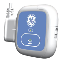
9.7.2 Magnetically-Mounted Temperature Sensors
The MMTS are connected to the CANbus connectors on the DIN rail. See Figure 9-3 for an
overview to the key parts of the product and Figure 9-24 below for a more detailed look
at the connection points.
Figure 9-24: CANbus Connection on the DIN rail
Due to the inability to reach the MMTS(s) once the transformer is energised,
communication with the sensor must be tested before the transformer is switched on (if
power to the product is available). Refer to Section 10.4 ‘Live Measurement’ of the ‘MA-
040 – DGA 900 Plus – Operator Guide’ and check that the Field Sensors Error for Top Oil
is not increasing by 1 every second and that the respective temperatures in the Field
Sensors are within the expected range.
 Loading...


