MDS 05-3438A01, Rev. F MDS 4790/9790 Series I/O Guide 31
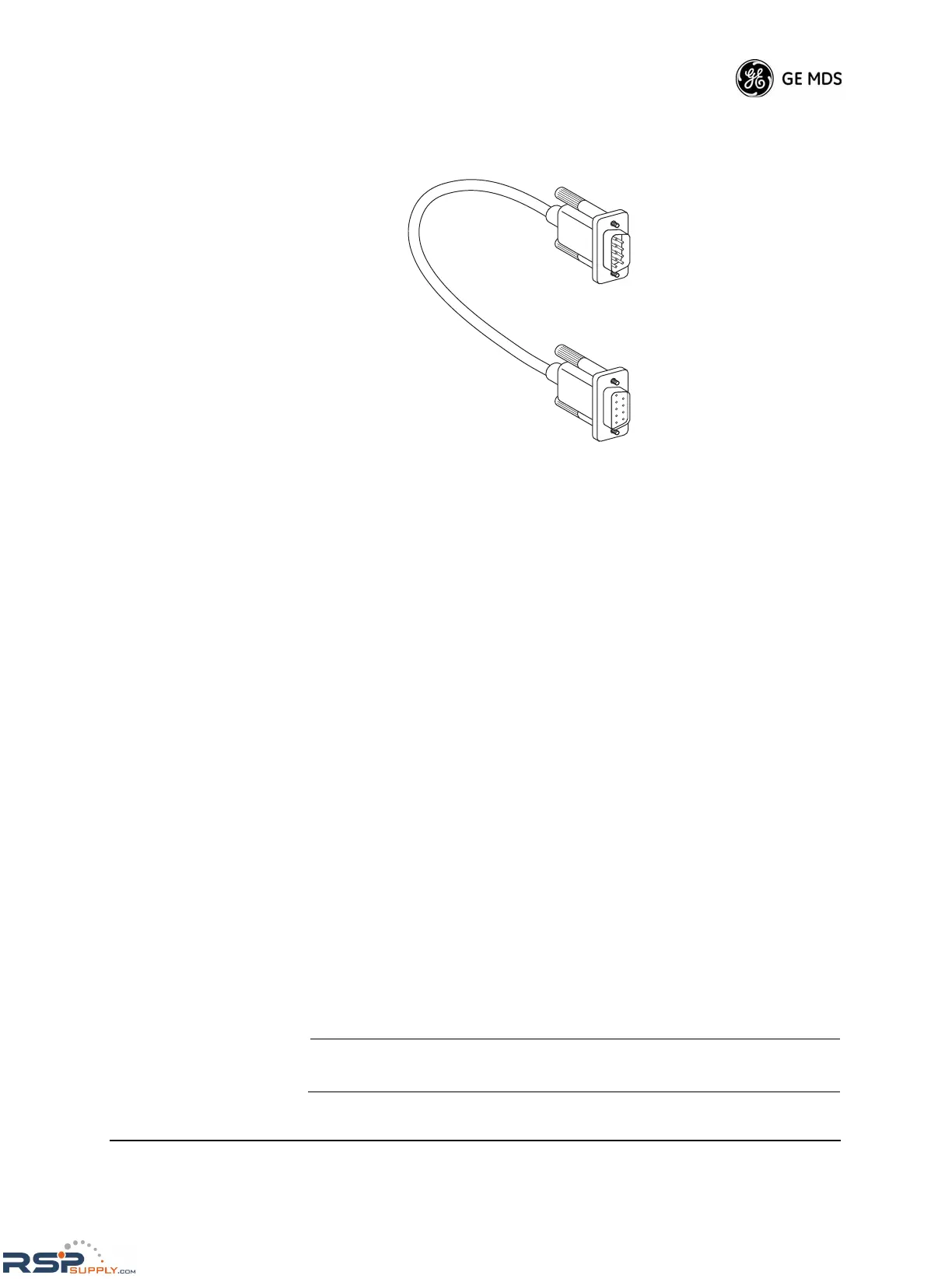
2. Connect a DB-9 to DB-9 cable (Figure 28) between
the PC and the radio’s rear panel DIAGNOSTIC PORT (Figure 27 on
Page 30).
Figure 28. PC Diagnostic Cable (DB-9 to DB-9)—
MDS P/N 97-1971A04
3. Install a terminal emulation program, such as HyperTerminal™ or
MDS InSite™ software (MDS P/N 03-3533A01), if such a program
is not already installed.
4. Launch the terminal program or diagnostics software.
a. If you are using InSite, follow the instructions given in the pro-
gram’s user guide.
b. If you are using a terminal emulation program:
Press the Space or Esc key several times, at one-second intervals,
until the > prompt is shown, indicating that the command
interface is ready to accept input. The diagnostic interface has an
automatic baud-rate detector which synchronize with your data
rate.
If the unit does not recognize your data interface arrangement,
try the following settings:
• Data Bits = Eight
• Parity = None
• Stop Bits = 1
• Data Rate = 9600 bps
• Flow Control = None
• Terminal Emulation/Mode = ANSI
NOTE: The DIAGNOSTIC PORT supports autobaud at 2400, 4800,
9600, 19200, and 38400 bps baud rates.
DB-9 MALE
CONNECTOR
TO RADIO
DB-9 FEMALE
CONNECTOR
TO PC

 Loading...