1-8 F650 Digital Bay Controller GEK-113000T
1.2 OVERVIEW 1 GETTING STARTED
1
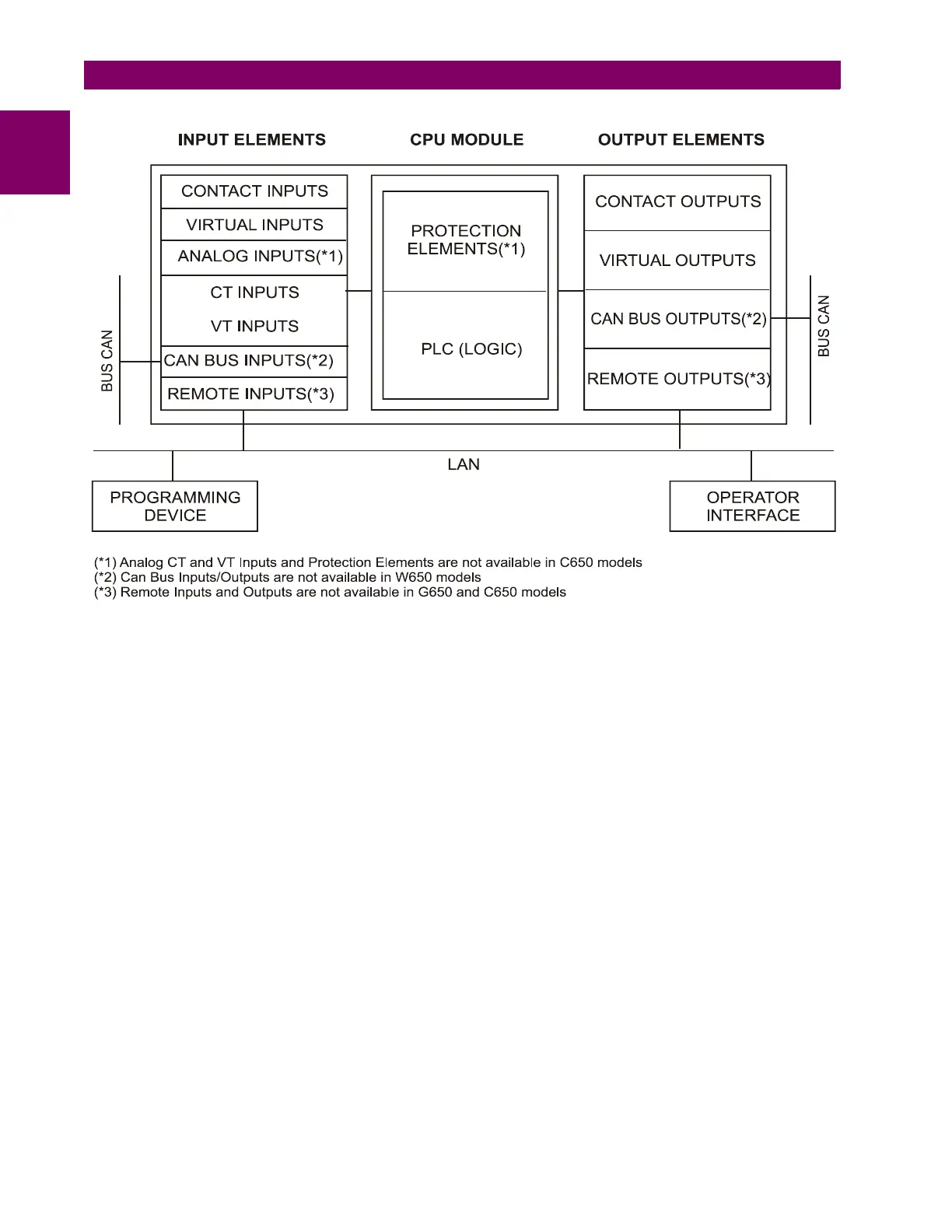
Figure 1–6: 650 CONCEPT BLOCK DIAGRAM
Contact Inputs/Outputs are signals associated to the physical input/output contacts in the relay
CT and VT inputs are signals coming from the inputs of current and voltage transformers, used for monitoring the power
system signals. Not available for C650 models.
CAN Bus Inputs/Outputs: are signals associated to physical input/output contacts from independent modules connected
to the 650 unit via a CAN Bus. Not available for W650 models.
PLC: Programmable Logic Controller. Control module that enables the unit configuration (assignment of inputs/outputs)
and the implementation of logic circuits.
Protection Elements: Relay protection elements, for example: Overcurrent, overvoltage, etc. Not available for C650
models.
Remote inputs and outputs provide a means of sharing digital point state information between remote devices using IEC
61850 GSSE and GOOSE messages. Not available for G650 and C650 models.
Analog Inputs are signals associated with transducers.

 Loading...


