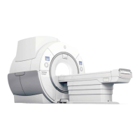
Illustration 2-15: Magnet Dimensions (as Shipped)
NOTE:
Dimensions are in inches. Bracketed dimensions are in millimeters.
Table 2-17: MR System Component Replacement Shipping Specifications
Component
W x D x H Weight
Notes
in. mm lbs kg
Replacement RF Body Coil 30 x 30 x 60 762 x 762 x 1524 255 116 Replacement coil is shipped in a pro‐
tective case. Weight & dimensions
are for coil & case.
Replacement VRMw Gradient
Coil Assembly on a Shipping
Cradle/Cart
39 x 99.84 x
59 See Note
991 x 2536 x 1499 3194 1449 Initial Gradient Coil Assembly is ship‐
ped installed in the Magnet. Shipping/
installation cart is used to install re‐
placement coil assembly only.
Gradient Coil Replacement
Tool Kit Crate
30 x 86 x 30 762 x 2184 x 762 750 340 This crate box includes Gradient In‐
sertion Kit
Note:
The replacement Gradient Coil Assembly weight is approximately 2205 lbs (1000 kg), the shipping cradle is 132 lbs (60 kg), and the Gradient
Coil Assembly shipping/installation cart weighs 855 lbs (389 kg). The coil assembly outside diameter x length dimensions are 35.7 x 57.2 in.
(908 x 1452 mm).
SIGNA Voyager Pre-Installation
Direction 5680008–1EN, Revision 2
56 11 MR System Shipping and Receiving

 Loading...