1-2 SPM Synchronous Motor Protection and Control GE Multilin
1.1 OVERVIEW 1 INTRODUCTION
1
The man-machine interface (MMI) consists of a backlit alphanumeric display and a keypad to accommodate
relay programming as well as viewing actual motor parameters which comprise:
• AC stator current
• Power factor
• DC field current
• DC field voltage
• DC field resistance
• Running time meter (RTM)
Statistical data includes number and type of trips.
The SPM performs a complete system check prior to starting the motor.
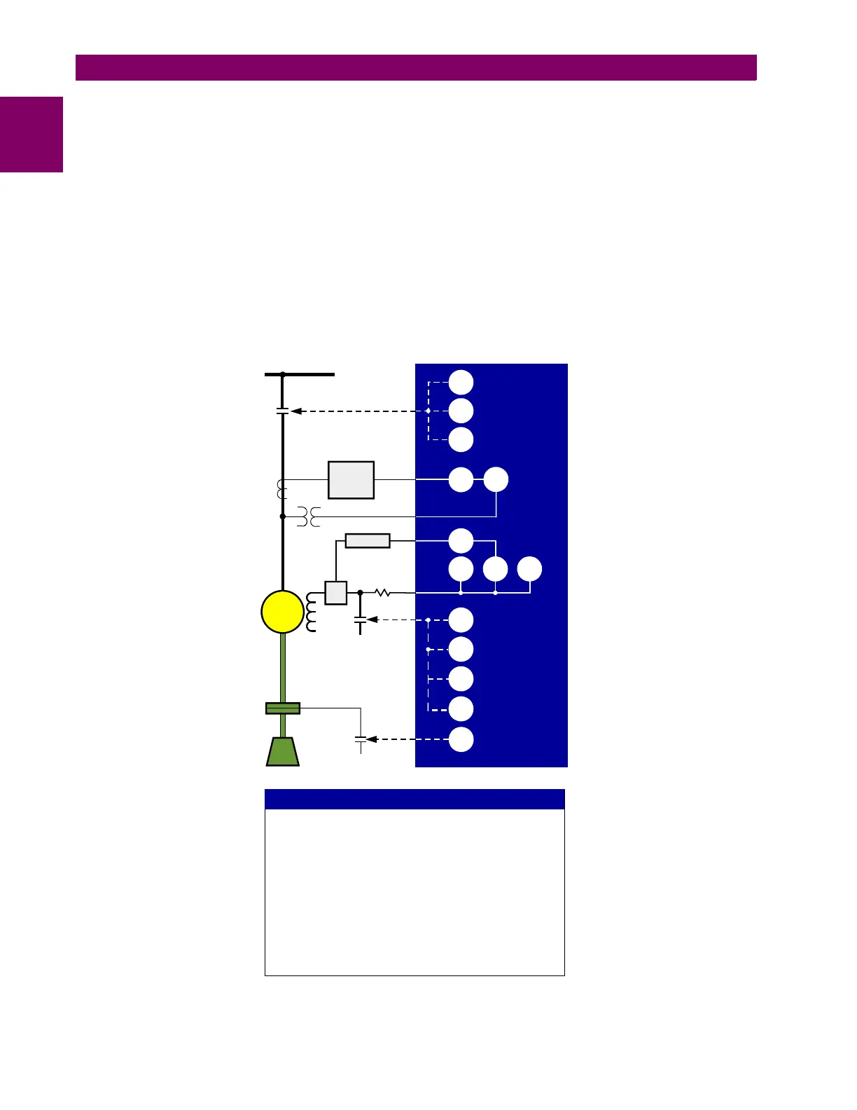
Figure 1–1: SINGLE LINE DIAGRAM
701767A9.CDR
MOTOR
LOAD
AC BUS
CLUTCH
COUPLING
DC SUPPLY
27 26F 95
96
56
95
48
94
86
94
48
55
SPM
Stator
Protection
(469)
Calibrator
DC
CT
37
50
I
AC
V
DC
I
DC
V
AC
ANSI DE VICE NU MB ER S
Fie ld o ve rte m p e ra ture
Un d e rv o lt a g e
U nd e rc urre nt or und e rp o we r
Inc o m p le te seq ue nc e
Insta nta ne o us o ve rc urre nt
Po w e r f a c t o r
Field application
Lo c k o u t
Tripping
Re l u c t a n c e t o r q u e sy n c . / re sy n c .
Autoloading relay
26F
27
37
48
50
55
56
86
94
95
96