GENERATOR
FREQUENCY
RADIO DIAL
SETTING
INDICATOR ADJUST REMARKS
1. 10.7 MHz Open
Scope at TP2.
Use Pad (See
Figure 1)
T1, T2, T3
Adjust for maximum gain and
symmetry. Repeat as necessary.
2. 10.7 MHz Open
Scope at TP3.
Use Pad (See
Figure 2)
T7, T8
Adjust for maximum gain and
symmetrical S-Curve
FM Generator - Modulated RF Radiated Signal
3. 109.0 MHz Open
Output Meter
Across Speaker
C15 Adjust for maximum.
4. 87.5 MHz Closed L4
Spread or compress coil wind-
ings slightly to raise or lower
frequency. Repeat Steps 3 and 4
5. 108.0 MHz Tune to Signal C1G, C1H Adjust for maximum.
6. 88 MHz Tune to Signal L1, L2
Spread or compress coil wind-
ings slightly to obtain optimum
alignment. Repeat Steps 5 and 6
FM AFC ALIGNMENT (R17 TRIM POT
1. Tune FM dial to a no signal area near the center of the FM Band (98 MHz).
2.
With the AFC switch S2 in OFF position, connect a high impedance voltmeter (Triplett 630-NS or equivalent) to S2 pin A1 and
measure the D.C. voltage. Note: Voltemeter chosen must not cause noise in FM Band which would cause incorrect alignment.
3.
Next connect voltmeter to S2 pin A2 and adjust R17 trim pot to the same voltage as measured in Step 2. Accuracy of voltage
adjustment to voltage measured in Step 2 should be better than +/- 5%.
CABINET DISASSEMBLY
Remove seven (7) cabinet back screws including
one (1) located in battery compartment.
1.
Remove Tuning, Treble, Bass and Loudness knobs.2.
Depress ON/OFF Power knob to the ON position.
Separate cabinet front from cabinet back at the bottom of
the cabinet, then carefully lift cabinet front upwards to
exit ON/OFF knob. (Note: Failure to depress knob
during this step will cause switch shaft to bend).
3.
TO SERVICE CIRCUIT BOARDS
To simplify servicing, troubleshoot from component side of
circuit board whenever possible, using the component layout
top view. To prevent damage to cabinet front and speaker,
it is suggested that speaker leads be disconnected at speaker
TO SERVICE CIRCUIT BOARDS, Cont'd
terminals and an 8 Ohm external test speaker be connected to
earphone jack while servicing radio.
Chassis mounting bracket with circuit boards and dial
cord stringing assembly can be removed from cabinet back
by removing screws #1 thru #4 (See Illustration)
For gurthur ease of servicing the bottom side of circuit
board, disconnect FM antenna lead at whip antenna.
1.
Removal of IF / Audio board from mounting bracket may
be necessary to remove a defective component from
certain areas of the circuit board. To remove circuit
board, remove five (5) screws, #5 thru #9,
and tilt chassis to expose conductor side of board.
2.
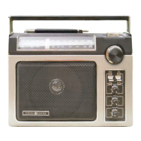
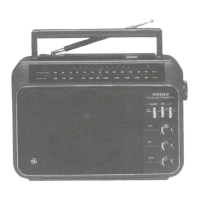
GE Superadio (1) Manual http://earmark.net/gesr/sr1_manual.ht
2 of 6 7/26/2014 3:34 P
 Loading...