GE MEDICAL SYSTEMS
D
IRECTION FK091075, REVISION 04 VIVID 3N PRO/EXPERT SERVICE MANUAL
8-28 Section 8-3 - Control Console Components Replacement
Section 8-3
Control Console Components Replacement
The Vivid 3N Pro/Expert Control Console comprises various components, the replacement procedures
for each of which is described as follows:
• Vivid 3N 15" Monitor - refer to Vivid 3N Monitor 15" Replacement - Procedure, as described
below.
• Vivid 3N 17" Monitor - refer to either of the following:
Samsung type: see Vivid 3N 17" Monitor Replacement - Procedure 1 on page 8 - 31.
Mag type: see Vivid 3N 17" Monitor Replacement - Procedure 2 on page 8 - 35.
• Keyboard -see Keyboard Replacement Procedure on page 8 - 38.
• Keypad -see Keypad Replacement Procedure on page 8 - 39.
• Trackball -see Trackball Replacement Procedure on page 8 - 43.
• Speakers -see Speaker Replacement Procedure on page 8 - 44.
8-3-1 Vivid 3N Monitor 15" Replacement - Procedure
NOTE: This describes the procedure for replacing a 15" monitor.
8-3-1-1 Tools
Use the appropriate Phillips-type screw drivers, as indicated in the Vivid 3N monitor 15" replacement
procedures.
8-3-1-2 Preparation
Shut down the Vivid 3N Pro/Expert ultrasound unit, as described in Chapter 3 - Installation.
8-3-1-3 Vivid 3N Monitor 15" Removal Procedure
1) Unplug the VGA cable and AC power cable from the rear of the control console.
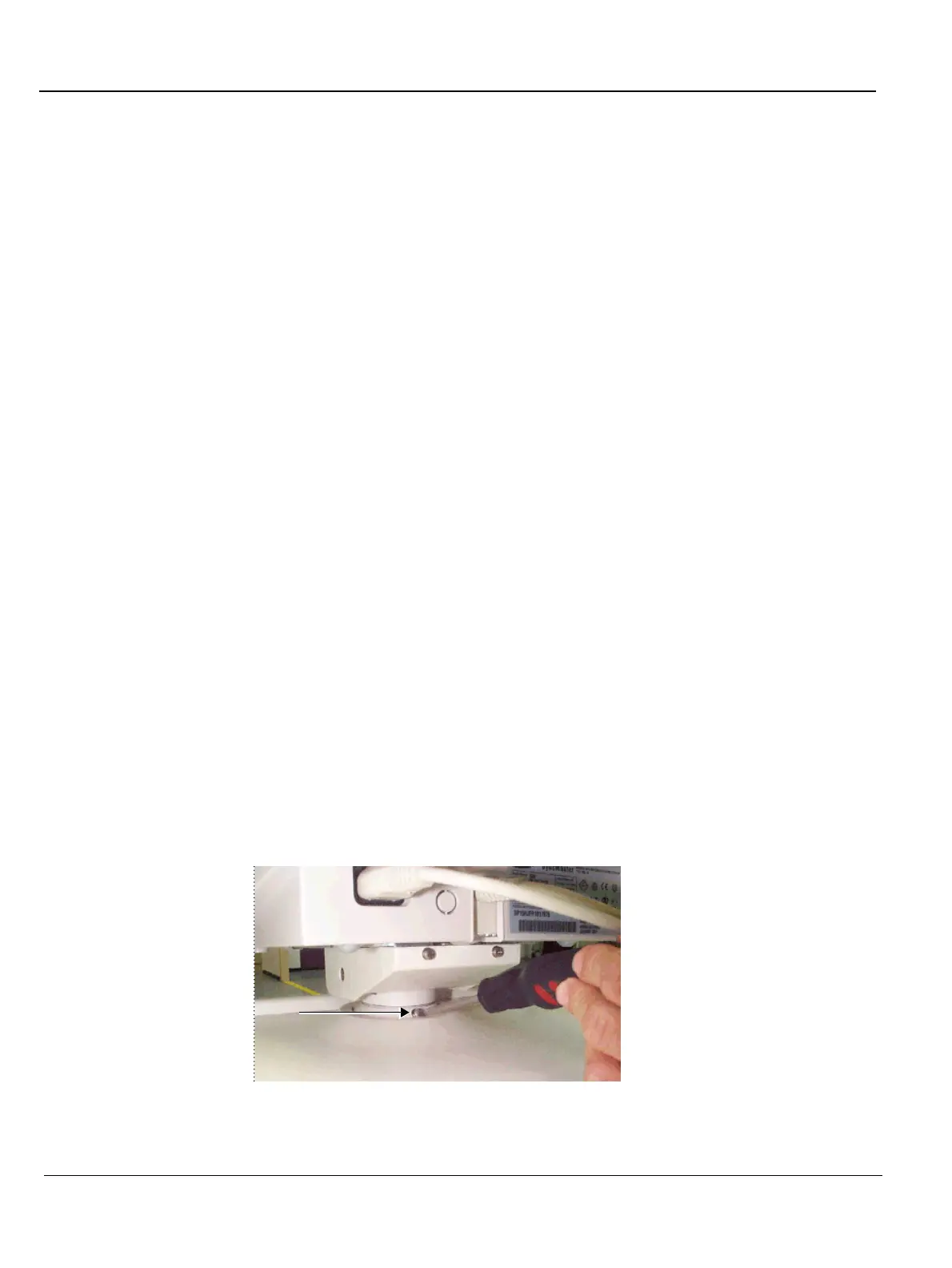
2) Loosen the screw located at the rear of the monitor base. Once this screw is loose, you can fully
rotate and lift the monitor out from the machine.
Figure 8-28 Vivid 3N Monitor Base Screw
 Loading...


