GE MEDICAL SYSTEMS
D
IRECTION FK091075, REVISION 04 VIVID 3N PRO/EXPERT SERVICE MANUAL
10-24 Section 10-7 - Electrical Safety Tests
10-7-6 Isolated Patient Lead (Source) Leakage – Lead-to-Ground
10-7-6-1 Definition
This test measures the current which would flow to Ground from any of the isolated ECG leads. The
meter simulates a patient who is connected to the monitoring equipment and is grounded by touching
some other grounded surface.
CAUTION: To avoid damaging the unit, never switch the polarity and the neutral status when the unit
is powered ON. Be sure to turn the unit power OFF before switching them, using the Polarity switch
and/or the Neutral switch.
10-7-6-2 Generic Procedure
Measurements should be made with the Ground Open and Closed, with the Vivid 3N unit ON and OFF,
and with the power line polarity Normal and Reversed. Record the highest reading. For each
combination, the operating controls (such as, the lead switch) should be operated to find the worst case
condition.
.
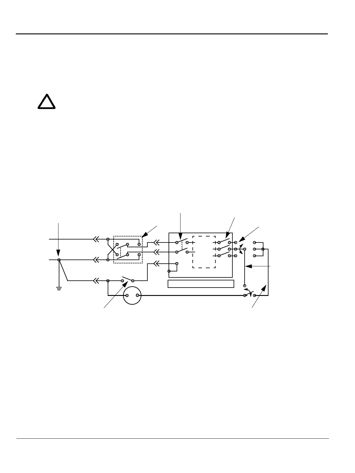
Figure 10-4 Test Circuit for Measuring Non-Isolated Patient Leads
POWER
OUTLET
H (Black)
N (White)
G (Green)
Internal
circuitry
Insulating surface
Polarity reversing switch
(use both positions)
Appliance power switch
(use both "OFF" and "ON" positions)
Patient connected leads
The connection is at service entrance
or on the supply side of a separately
derived system
Building
Ground
Grounding contact switch (use in both
"open" and "closed" positions)
Current meter
H = Hot
N = Neutral (grounded)
G = Grounding conductor
H
N
G
Patient lead selector switch (if any)
(activated as required)
Appliance
Between each patient
lead and Ground
 Loading...


