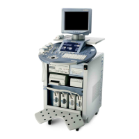
GE MEDICAL SYSTEMS - KRETZTECHNIK RAFT VOLUSON® 730PRO / 730PROV (BT´04)
D
IRECTION KTI105947, REVISION 2 SERVICE MANUAL
4-20 Section 4-4 - Functional Checks
4-4-5-3 Sub Menu
For further details refer to the Voluson® 730Pro / 730ProV Basic User Manual, Chapter 11.
Figure 4-14 3D/4D Sub Menu
Table 4-9 Sub Menus
Step Task Expected Results
1
RENDER VIEW
DIRECTION
To select the desired Render View Direction (green line symbolizes direction of the view).
Note:
The Render View Direction keys are not available in Static 3D Sectional Planes.
2
GRAY/CHROMA
Depending on individual requirements a “harder” or “softer” image can be obtained.
3
3D/4D INFO
On/Off switch to show full or reduced Image Info parameter on screen.
4
COLOR OFF
On/Off switch to show an acquired 3D+CFM or 3D+PD image with or without the color
information.
5
SRI *
Speckle Reduction Imaging (SRI) can be activated in all 3D/4D modes (except Full size
display) to reduce speckle which interferes with the sectional planes (A, B and C).
Note: The rendered 3D image is not affect.
6
BACKGR.
Adjusts the contrast of the screen background from dark to bright.
Note:
This key is not available in Static 3D Sectional Planes mode.
7
CONTR. POS
To set the start point of the gamma curve bending. (Graphic display on screen)
Note:
This key is not available in Static 3D Sectional Planes mode.
8
CONTRAST
To set the contrast of the bending. (Graphic display on screen)
Note:
This key is not available in Static 3D Sectional Planes mode.
9
POWER THRESH.
Only available if a 3D+CFM or a 3D+PD image is acquired.
Note:
This key is only available if a 3D+CFM or a 3D+PD image is acquired.
10
BALANCE
Only available if a 3D+CFM or a 3D+PD image is acquired.
Note:
This key is only available if a 3D+CFM or a 3D+PD image is acquired.
11
PROBE ORIENTATION
Adjust and activate the display of direction markers at border of the image.
(at systems that were upgraded to
BT´05 only)

 Loading...