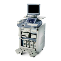
GE MEDICAL SYSTEMS - KRETZTECHNIK RAFT VOLUSON® 730PRO / 730PROV (BT´04)
D
IRECTION KTI105947, REVISION 2 SERVICE MANUAL
7-4 Section 7-3 - Check Points Voltages
Section 7-3
Check Points Voltages
7-3-1 How to check power
Figure 7-2 Diagnostic LED´s and corresponding voltage check points
DVM
Additionally check 59V/DC
(Power connection-cable
(Pin 2 and 3 = +3.3V ; Pin 1 = GND)
2
3
1
Open the locking, flap the service lid on the back
of theVoluson® 730Pro / 730ProV upwards, and
check the status of the Diagnostic LED´s.
LED 6
LED 5
LED 4
LED 1
LED 2
LED 3
In case of problems, check the above voltages
with a Digital Volt Meter (DVM) to Ground.
(+15V)
(-15V)
(+3.3V)
(+5V)
(+12V)
LED 1, 2 and 5
ECG connector
8
1
9
15
Pin 15
(+5V)
Pin 13
(+15V)
Pin 11
(-15V)
LED 4
AUX Supply (= GEM Power connector)
LED 6
Footswitch connector on Power Supply Module (CPN)
on Backpanel of GEF-Box
Pin 1
(+12V)
(Fan)
Pin 4
(+5V)
Location of fuses on CPE;
see: Section 5-11-3-1 on page 5-45
on Backpanel of GEF-Box
from CPN to GEF)
CPN6
CPN80
2
3
1
LED orange (at CPN80 only)
visual check for 59V:
orange LED (at CPN80 power supply) is lightening

 Loading...