GE RAFT VOLUSON™ P8 / VOLUSON™ P6
DIRECTION 5723243, R
EVISION 6 DRAFT (MAY 23, 2018) BASIC SERVICE MANUAL
8-60 Section 8-19 - Replacement of OPIO Plastic lower cover assy
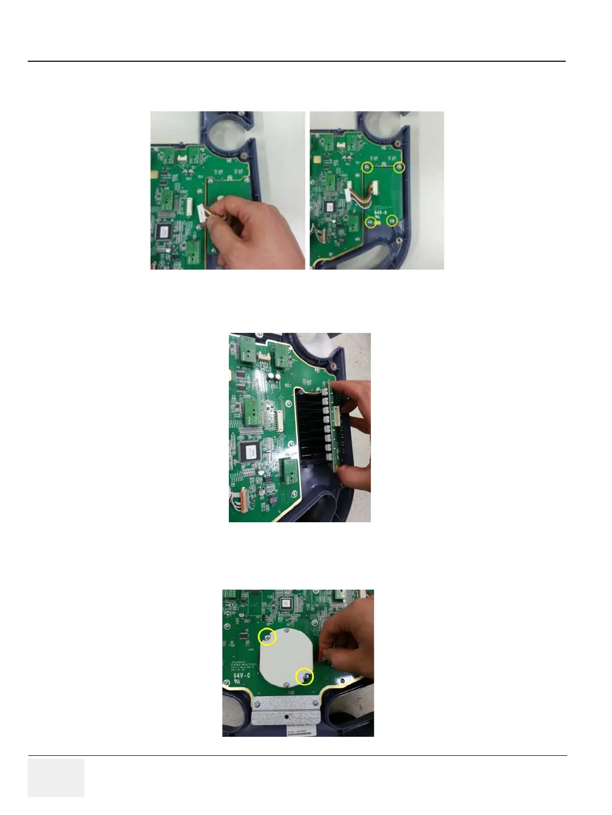
7.) Unscrew 4 screws of TGC control circuit board after disconnecting the cable. Refer to the figures
below.
8.) Pull out the circuit board. Refer to the figure below.
9.) Unscrew 2 screws on trackball and disconnect the cable to remove the trackball. Then remove
trackball. Refer to the figure below.
Figure 8-78 Unscrewing 4 screws of TGC control circuit board
Figure 8-79 Pulling out the circuit board
Figure 8-80 Unscrewing 2 screws on trackball and disconnecting the cable
 Loading...


