GE DRAFT VOLUSON™ P8 / VOLUSON™ P6
DIRECTION 5723243, R
EVISION 6 DRAFT (MAY 23, 2018) BASIC SERVICE MANUAL
Chapter 8 - Replacement Procedures 8-143
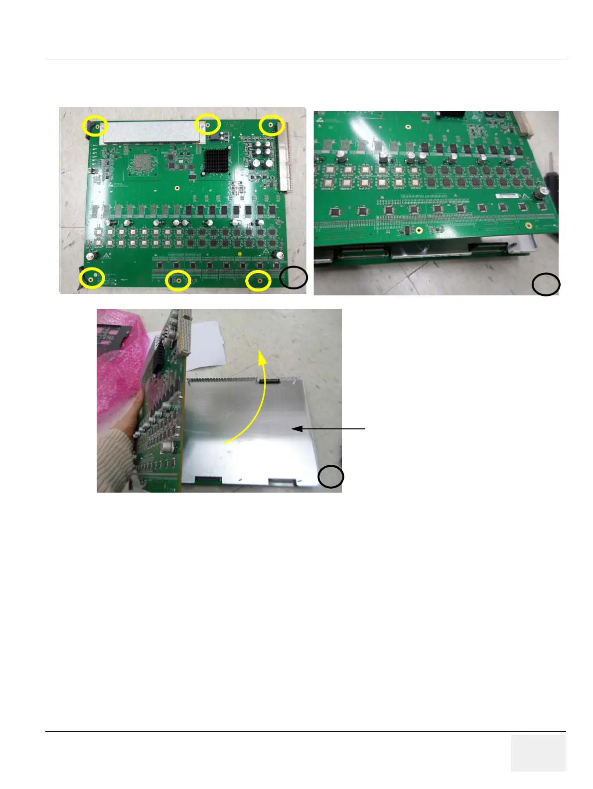
2.) Unscrew 6 screws.
3.) Remove DBM64 from the EMI SHIELD BRACKET.
8-45-5 Installation Procedure
1.) Install the new parts in the reverse order of removal.
2.) Perform: FRU8-36: Replacement of the DBM64 - Functional Tests..
Figure 8-204 Unscrewing 6 screws and removing the EMI SHIELD BRACKET
 Loading...


