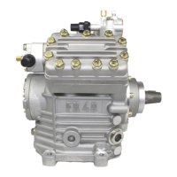
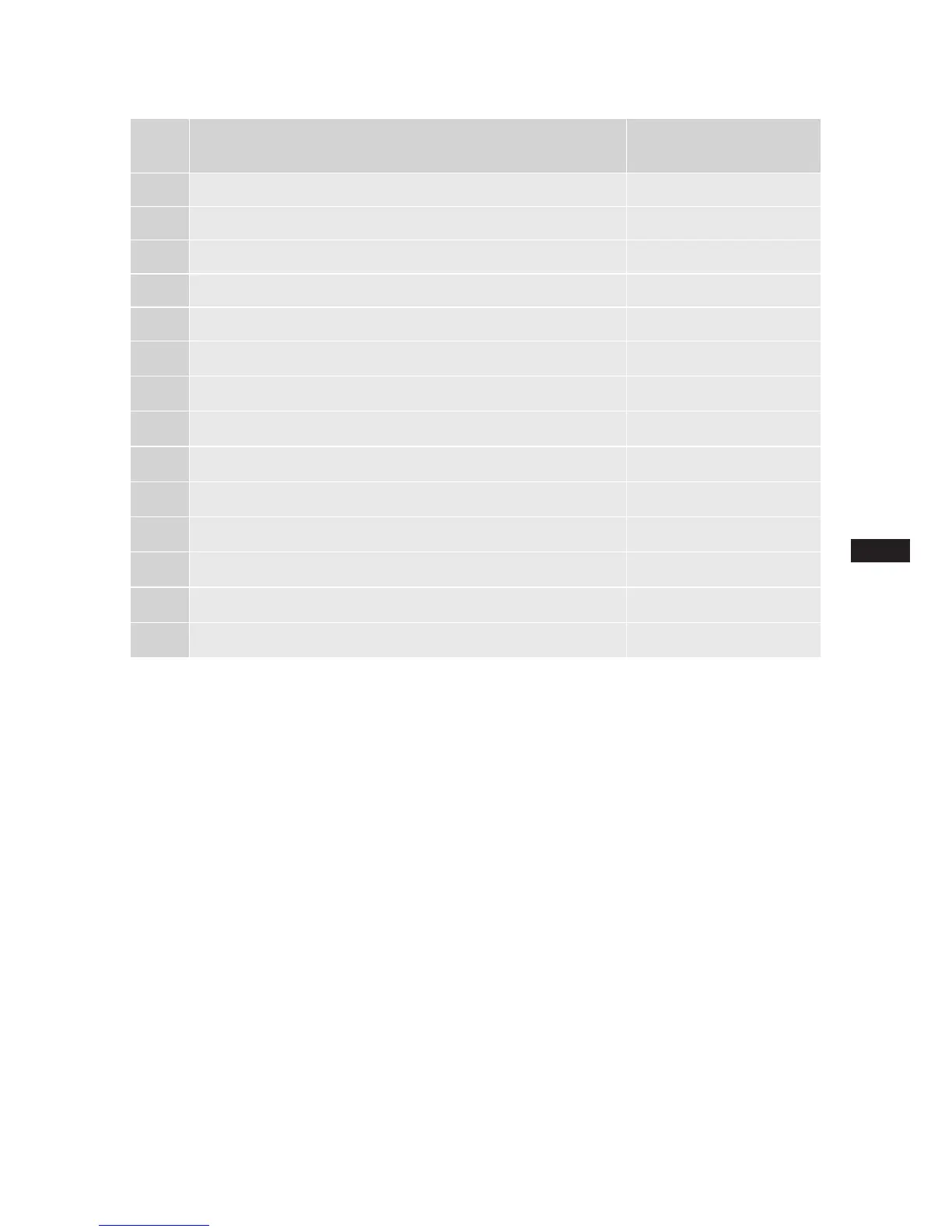
9| Dimensions and connections
1)
=Noconnectionavailableasstandard.
Availableonrequest(ConnectionM22x1,5)
SV
DV
Suction line
Discharge line
see technical data, Chapter 8
A
Connection suction side, not lockable
1
/
8
" NPTF
A1
Connection suction side, lockable
7
/
16
" UNF
B
Connection discharge side, not lockable
1
/
8
" NPTF
B1
Connection discharge side, lockable
7
/
16
" UNF
C
Connection oil pressure safety switch OIL
1
/
8
" NPTF
D
Connection oil pressure safety switch LP
1
/
8
" NPTF
E
Connection oil pressure gauge
1
/
8
" NPTF
F
Oil drain
1
/
4
" NPTF
G
Opt. connection for oil sump heater
1)
H
Oil charge plug
1
/
4
" NPTF
K
Sight glass 2 x 1
1
/
8
"- 18 UNEF
L
Connection thermal protection thermostat
1
/
8
" NPTF
M
Oillter M22 x 1.5
SV1
Opt. connection for suction line valve - -
 Loading...