80018C_MSW_2400-2500-Profibus_1209_ENG
Page 15
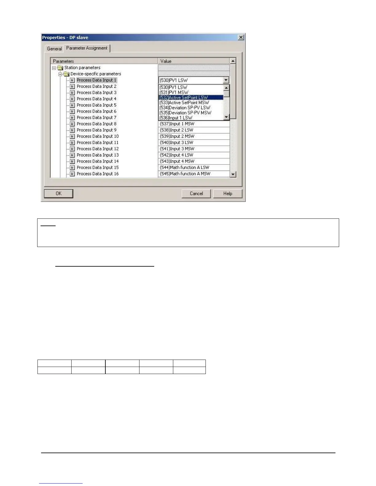
Clicking the fields in the “Value”
column (on the right) lets you
modify the default parameter as
required by opening a pull-down
menu to choose preset
variables.
Use the vertical scroll bar to
display the “Process Data
Output” variables and thereby
change the default value by
choosing one of the alternatives
provided.
Note:
If you decide to use FC “PD_2400_2500” (see paragraph 5.3.2), the process data of the INPUT area are ciclically
read and written in the assigned data block, while the process data of the OUTPUT area are written in the
instrument at the same time if at least one datum is changed in the assigned data block.
5.2.1 DATA IN WHOLE DOUBLE FORMAT
Process data in whole double format are represented with bits from 0 to 15 in the word with LSW suffix and with
bits from 16 to 31 in the word with MSW suffix.
Siemens uses byte addressing for the various memory areas: in a word, the most significant byte is the one with
the lowest address, in a double word the most significant word is the one with the lowest address.
For example if we want to read the process variable 1 (PV1) associated to instrument PDI 1 and 2, we will have to
assign the word “(531)PV1 MSW” to PDI 1 and the word “(530)PV1 LSW “ to PDI 2 so that the reading of the
double word is correct:
PED 263 = PV1
Bytes in the PED have the following order:
 Loading...