80018C_MSW_2400-2500-Profibus_1209_ENG
Page 17
If UDT “2400_2500DataPD “ is used the resulting data block will have the following composition:
DBx.DBB0 Trigger (reserved)
DBx.DBB0 Counter (reserved)
DBx.DBB2 .. ..DBx.DBB8 Request of PARAMETRICAL DATA
DBx.DBB9 .. ..DBx.DBB15 Reply of PARAMETRICAL DATA
DBx.DBW16
Error word in the writing operation of the consistency area
(SFC15, DPWR_DAT)(please refer to SIEMENS STEP7 manual for error codes
)
DBx.DBW18
Error word in the reading operation of the consistency area
(SFC14, DPRD_DAT)(please refer to SIEMENS STEP7 manual for error codes)
DBx.DBW20 INPUT 1 PROCESS DATUM
DBx.DBW22 INPUT 2 PROCESS DATUM
≈ ≈
DBx.DBW50 INPUT 16 PROCESS DATUM
DBx.DBW52 OUTPUT 1 PROCESS DATUM
DBx.DBW54 OUTPUT 2 PROCESS DATUM
≈ ≈
DBx.DBW82 OUTPUT 16 PROCESS DATUM
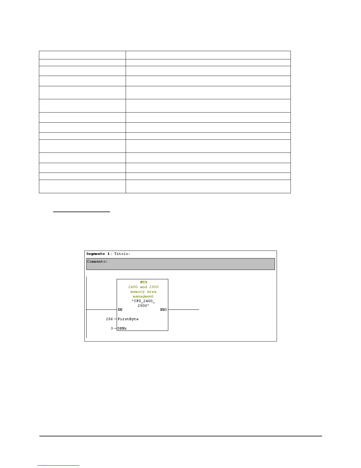
5.3.2 FC3 “CFG 2400 2500”
This function makes available, in the data block created with UDT described in the previous paragraph, the
instrument Parametrical Data necessary for the FB1 operation (see paragraph 5.3.4)
FC must be called up in the OB1, without conditions, so that each scanning updates data.
Two input parameters are requested:
FirstByte (INT):
It is the first memory address assigned in the instrument hardware configuration
DBNr (INT):
It is the number of data block created with UDT4 or UDT5 in order to keep the whole area of exchange data.
 Loading...