EasyManua.ls Logo

gefran VDI100 Series User Manual

gefran VDI100 Series
362 pages
To Next Page IconTo Next Page
To Previous Page IconTo Previous Page
Page #249 background imageLoading...
Page #249 background image
00040 - 09999: □□□□ (Integer only e.g. 1000 )
10001 - 19999: □□□. □ (1 decimal place e.g. 10.0)
20001 - 29999: □□. □□ (2 decimal places, e.g. 10.00)
30001 - 39999: □. □□□ (3 decimal places, e.g. 10.000)
<example>
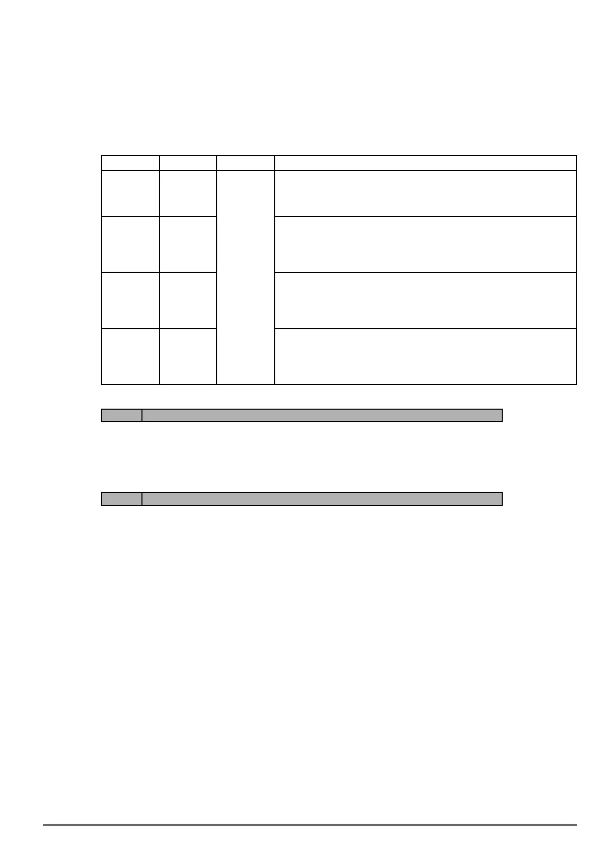
16-03 Display Display unit Display example
00040
09999
□□□□
use 16-04
setting
Example:
100 % speed is 0200
> set 16-03=00200 (from 05-01, 06-01 to 06-15, set range from 0040 to 9999).
> set 16-04=0 (no unit)
10001
19999
□□□. □
Example:
100 % speed is 200.0 CFM
> set 16-03=12000 (05-01, 06-01 to 06-15, set range from 0000 to 9999).
> set 16-04=2 (CFM)
> 60% speed will be displayed as 120.0 CFM
20001
29999
□□. □□
Example:
100 % speed is 65.00ºC
> set 16-03=26500 (05-01, 06-01 to 06-15, set range from 0000 to 9999)
> set 16-04=20 (ºC)
> 60% of speed is displayed as 39.00 ºC
30001
39999
□. □□□
Example:
100 % speed is 2.555 m/s
> set 16-03=32555
> set 16-04=14 (m/s)
> 60% speed is displayed as 1.533 m/s
Code Parameter Name / Range
16-05 LCD backlight
0~7
Adjust the screen contrast of the digital operator. If it is set to 0, the screen backlight is turned off.
Code Parameter Name / Range
16-07 Copy function selection
0: Do not copy parameter
1: Read inverter parameters and save to the keypad
2: Write the keypad parameters to inverter
3: Compare parameters of inverter and keypad
16-08 Selection of allowing reading
0: Do not allow to read inverter parameters and save to the keypad
1: Allow to read inverter parameters and save to the keypad
LCD digital operator with built-in memory (EEPROM) can be used to store and retrieve parameters:
(1) Read: Save inverter parameters to the digital operator (INV → OP).
(2) Write: Write the parameters from the digital operator to the inverter and save (OP → INV).
(3) Verify: Compare the inverter parameters against the parameters in the digital operator.
16-07=0: No action
16-07=1: Read (all parameters are copied from the inverter to the keypad).
16-07=2: Write (all parameter are copied from the keypad to the inverter).
16-07=3: Verify (Compare the set value of the inverter to the parameter of the digital operator).
Set 16-08 = 0, to prevent the saved parameter data stored in the digital operator from accidentally being over-
written.
VDI100 • Instruction manual 249

Table of Contents

Questions and Answers:

gefran VDI100 Series Specifications

General IconGeneral
Brandgefran
ModelVDI100 Series
CategoryInverter
LanguageEnglish

Summary

1. Safety Precautions

1.2. Before Supplying Power to the Inverter

Ensures correct wiring and warns against connecting input supply to output terminals.

1.3. Wiring / Câblage

Details proper grounding, RCD compliance, and dielectric withstand test precautions.

1.4. Before Operation

Covers model matching, carrier frequency adjustment for long cables, and cover installation.

1.6. Operation / Opération

Provides guidelines for safe inverter operation, including cover installation, motor connection, and fan operation.

1.7. Maintenance, Inspection and Replacement

Details procedures for maintenance, inspection, and replacement, emphasizing safety precautions.

2. Model Description

2.1. Nameplate Data

Essential for verifying inverter nameplate and ensuring correct rating for application.

2.2. Inverter Models – Motor Power Rating (HD – Heavy Duty)

Lists inverter models and their corresponding applied motor power ratings for Heavy Duty applications.

3. Environment and Installation

3.1. Environment

Specifies operating temperature, storage, humidity, altitude, installation site, and shock conditions.

3.2. Installation

Details inverter installation in an upright position and required surrounding space for heat dissipation.

3.3. External View

Illustrates the external appearance of different inverter sizes, labeling key components.

3.4. Warning Labels

Highlights important warning information located on the front cover that must be read upon installation.

3.5. Removing the Front Cover and Keypad

Explains how to remove the front cover to access terminals for wiring connections.

3.6. Wire Gauges and Tightening Torque

Provides UL approved wire gauges, crimp terminals, and fastening torque specifications.

3.8. General Wiring Diagram

Illustrates the basic power and control circuit terminal connections for the inverter.

3.10. Power Terminals

Specifies terminal connections for input power, inverter output, and ground.

3.12. Inverter Wiring

Provides wiring precautions, power input terminal details, and grounding requirements.

4. Keypad and Programming Functions

4.1. LED Keypad (KB-LED-VDI100)

Details the LED keypad display, its keys, and their functions for inverter operation and parameter setting.

4.2. LCD Keypad (KB-LCD-VDI100)

Explains the LCD keypad display, its keys, and the menu structure for programming and monitoring.

4.3. Parameters

Provides a comprehensive list of all inverter parameters categorized into groups for easy access and configuration.

Related product manuals