Chapter 5 - Controls & Safety Equipment
909793/BP0805 16 Printed in U.S.A.
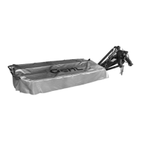
1 - Release Lever
Fig. 5: Releasing Protective Cover Lock
1
To lower the cover and place it in the operating position:
1. Lower the cutterbar into the operating position
(refer to the transport locks section later in this
chapter for proper procedure).
2. Use your fingers or the palm of your hand to apply
pressure on the lever (Fig. 5, Ref. 1) to release the
protective cover lock.
3. While applying pressure to the lever, fold the cov-
er front half forward and down as shown.
4. Release the lever and continue to fold the cover
down until it locks into the operating position.
TRANSPORT & OPERATING
POSITION LOCKS (Fig. 6)
Stop lock (Ref. 1) - When in the operating position, this
lock is provided to prevent raising the cutterbar to the
transport position.
Transport hook- type lock (Ref. 2) - When the cutterbar
is moved into the transport position, this lock is
automatically engaged to prevent the cutterbar from
lowering.
Cylinder stroke limiter Lock (Ref. 5) - When in the
operating position and with the hydraulic control set to
“float” position, this lock prevents the cylinder rod
clevis from bottoming against the cylinder packing
gland.
All three of these locks are released by pulling on the
rope release mechanism (Ref. 4).
NOTE: Refer to the Transporting chapter for
proper procedures to place the cutterbar in the
transport and operating positions.
CAUTION
BEFORE transporting the disc mower on a
public highway or from one field to another,
BE SURE the transport hook lock is properly
engaged.
1 - Stop Lock
2 - Hook-type Transport Lock
3 - Rope Control Lift Points
Fig. 6: Transport & Operating Position Locks
1
5
1
4
4 - Rope Control
5 - Cylinder Stroke Limiter
6 - Parking Lock
2
2
3
4
3
5
6
 Loading...