❏ ❏
❏ ❏
❏ 2
DRW
APP.
CKD
WRITTEN CONSENT BY GENERALMUSIC.
OR REPRODUCE THIS DOCUMENT WITHOUT
ALL RIGHTS ARE RESERVED, NO COPIES
GENERALMUSIC S.p.A. ITALY
PA RT :
DWG#
DISK:
REV:
PCB#
R. Morbidi
I. Vitri
G. Boccato 500949
22/11/01
Opening Instructions
Video Board Installation Instructions
1/1
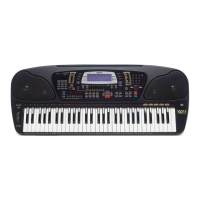
Opening Instructions
1.
Turn off and disconnect the keyboard from mains line.
Carefully turn the keyboard over and remove all the screws
indicated by the arrows as shown in figure below.
Hold the top and bottom chassis tightly and turn it the right
way up.
Raise the lid and turn it vertically taking care not to
disconnect the cables.
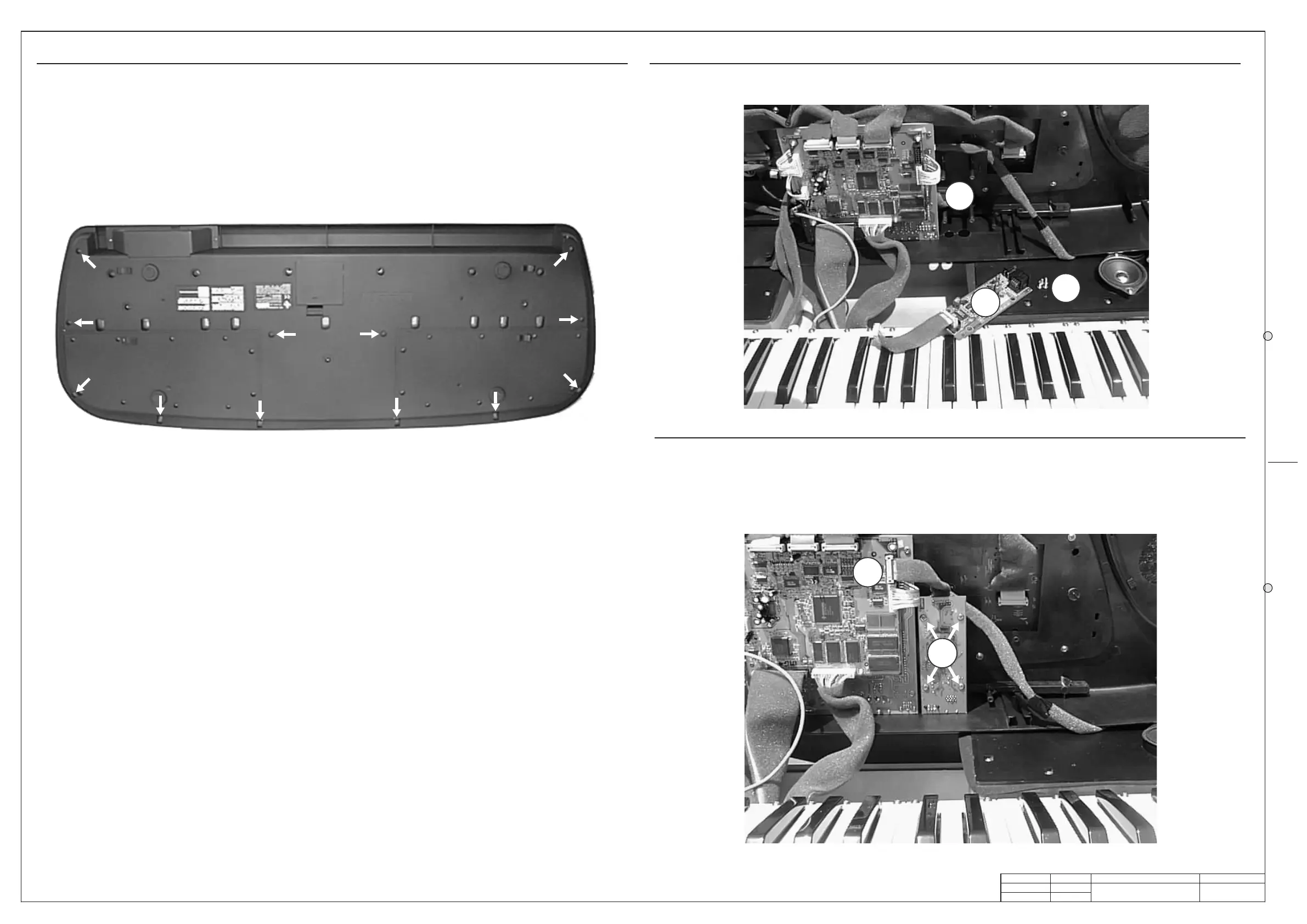
2.
Place the Video Board (A) on its location (B) at the right of
the other boards as shown in figure below.
3.
Fix the Video Board (A) on the columns using the screws
(C), connect the cable in predisposed connector (D) as
shown in figure below.
4.
Close the instrument and check the properly operation
connecting a television and following the instructions on the
owner's manual.
A
B
C
D
C
Video Board Installation Instructions
TEST PROCEDURE
This procedure are not intended to repair a fault but only to check the proper instrument operations
after a repairing execution. The procedures that follow must be executed in the order specified.
Instrument and Tools
1) Dual trace oscilloscope.
2) Midi cable.
3) Television with RGB and S-VHS input sockets compatible with PAL and NTSC standards.
4) DIN/SCART, DIN/RCA and S-VHS cables.
5) Volume and Damper pedal.
6) Latest version of the appropriate Operating System Disk.
7) N.2 stereo jack plug.
Setup
✓ Connect the television by RGB and S-VHS sockets.
✓ Connect the stereo jack to the PHONES and AUX outputs.
Operating System Check
✓ Turn on the instrument.
✓ Press MIDI/GENERAL for about 2 sec until the display shows "Damper Pedal:...", press PAGE>
until display shows "O.S. Release:" follows by the O.S. release date loaded into flash memory.
✓ If an update is required put the Operating System disk into the disk drive and turn on again the
keyboard, the display shows “LOAD O.S.” then press ENTER to confirm.
NOTE: After any servicing operation an operating system re-loading is recommended.
Video Check & Adjustment (Optional)
✓ The instrument starts with the video output set on PAL mode by default. Set TV input on RGB
mode, on the TV screen must appear the welcome message:
GEM WK1
Keyboard
✓ Press MIDI/GENERAL for about 2 sec until the display shows "Damper Pedal:...", press PAGE>
until display shows "Video Type: PAL (Europe)” , press TEMPO/DATA> to select “NTSC (USA)”, on
TV screen must appear the above message wrote larger than in the previous PAL setting.
✓ Disconnect or deselect the RGB input and select the S-VHS input (YC3) on TV.
✓ Adjust if necessary the colours and the flicker on TV rotating the C12 capacitor trimmer.
✓ Restore "PAL (Europe)” pressing TEMPO/DATA>.
✓ Adjust if necessary the colours and the flicker on TV rotating the C11 capacitor trimmer.
✓ Press ESCAPE button.
System Reset
✓ Press UPPER 1 button and 1, 2, and 3 of numeric keypad simultaneously to reset the instrument,
the display shows “System RESET”. This procedure restore the initial manufacturer memory
configuration.
Keyboard Check
✓ Play all white and black keys taking care to the uniformity of the dynamic response.
Controls Panel Check
✓ Make sure that each single push button on the control panel operates correctly checking the
correspondance with the display visualization if exist and/or the respective LED.
Ram Back Up Check
✓ Press TRANSPOSE “#” and display shows below TRANSPOSE “1”.
✓ Switch off the instrument and wait at least 20 sec. When you switch on the instrument be sure
display shows the same “TRANSPOSE” number.
✓ NOTE: the instrument have an internal re-chargeable NiCd battery that insures the data backup
for a maximum of 30 days, therefore it is recommended to hold switched on the instrument for at
least 8-10 hours after a long time of inactivity.
Headphones Check
Check the level from the output sockets as follow:
✓ Connect the dual trace oscilloscope to the tip and sleeve contacts of the stereo jack plugged into
PHONES 2, set it at 2ms/div. 2V/div.
✓ Press 68 on SOUNDS numeric keypad, the display will show "68:OBOE".
✓ Disable REV/CHO by pressing it correspondent button.
✓ Set MASTER VOLUME potentiometer to its maximum.
✓ Play the note key C4 (61 note keyboards normally starts from C2) and verify with the oscilloscope
the output levels: their must be 5.5±0.5Vpp.
✓ Move the oscilloscope probes to the stereo jack plugged into AUX OUTPUTS, the scope shows
two traces with 0.8Vpp ±5% each.
Pedals Check
✓ Plug in the PEDAL VOLUME to its socket, it vary the level from 0 (no sound) to the level set by
MASTER VOLUME potentiometer.
✓ Plug in the switch pedal to the DAMPER jack socket, press down the pedal and then press a note
key: the instrument plays the note, release the note key and the sound holds on, release the pedal
and the sound shuts off.
✓ NOTE: the type of pedal (normally closed or normally open) is recognized at the moment of a
SysReset or when the instrument is switched on, the instrument asummes that the pedal is
normally open if none pedal is plugged into the socket, this is the reason because a pedal
normally closed plugged after you have switched on the instrument operates in opposite way.
Midi In/Out and Computer Socket Check
✓ Set on UPPER 1 section only and make a loop between MIDI OUT and IN by means the midi
cable.
✓ Set UPPER 1 to local off by select MIDI/GENERAL for about 2 sec until the display shows
"Damper Pedal:..."
✓ Press PAGE> until display shows "MIDI local:...".
✓ Turn off track 8 by select F8, the respective "ON" text flashes, and press <TEMPO/DATA then
display shows "--".
✓ Now each keyboard event will be send thru the midi external loop and played by the internal
generation.
✓ Restore track 8 to local on pressing TEMPO/DATA> then display shows "ON".
✓ Press 4 times <PAGE until display shows “Serial Computer: OFF”.
✓ Press CURSOR 3 times and then press TEMPO/DATA> until display shows “MAC”
✓ Connect the CH1 probe of the oscilloscope at PIN 1 of the COMPUTER socket and its ground
clip at PIN 4, set it at 200uS/div. 2V/div.: the trace must show a 1MHz signal with 5V of amplitude
centred on 0V (±2.5V).
✓ Connect the CH2 probe of the oscilloscope at PIN 6 of the COMPUTER socket and its ground
clip at PIN 4, set it at 500uS/div. 10V/div.: playing some notes on the keyboard, the CH2
oscilloscope trace must show a sequence of pulses with 24V of amplitude centred on 0V.
✓ Pressing TEMPO/DATA> select “PC1” or “PC2” to configure the instrument link for a PC.
✓ Playing some notes on the keyboard you must see the same previous pulses onto the
oscilloscope screen.
✓ Press ESCAPE.
Floppy Disk Check
✓ Insert a 3.5" diskette containing a standard midi file .MID.
✓ Press FLOPPY DISK, display shows "DIRECT: songname.MID", pressing TEMPO/DATA> the
display will show: "LOAD:songname.MID", press ENTER to confirm, the display shows "Loading
into memory" and the keyboard stops during this process.
✓ Press START/STOP and the song will start to play.
✓ Press again FLOPPY DISK, display shows "DIRECT: songname.MID", pressing TEMPO/DATA>
two times the display will show: "SAVE: Song SMF Perform", press ENTER 3 times to confirm, the
display shows "Saving on disk" and the keyboard stops during this process.
Sound ROM test
✓ Select sound 00 and play some note checking its out, repeat the check with sound 33, 66, 99,
127, select SINGLE TOUCH PLAY, press START DRUM and play a chord on the keyboard left
part: check the correct style and sound; repeat the check for styles 33, 66, 88 also.
Reliability Check
Before reassembling the instrument and before deliver it to the user, it is a goal verify its reliability:
To do that switch it off, or leaving it switched on but operating with greatest caution, carefully shake
the boards and connections inside it using an insulated tool (for example the handle of the
screwdriver) to find wrong contacts and so on.
Turn on the instrument and verify that it operates correctly.
 Loading...