Gems Sensors & Controls
| One Cowles Road | Plainville, CT 06062-1198
Telephone: 1-800-378-1600 | Email: info@gemssensors.com | www.GemsSensors.com
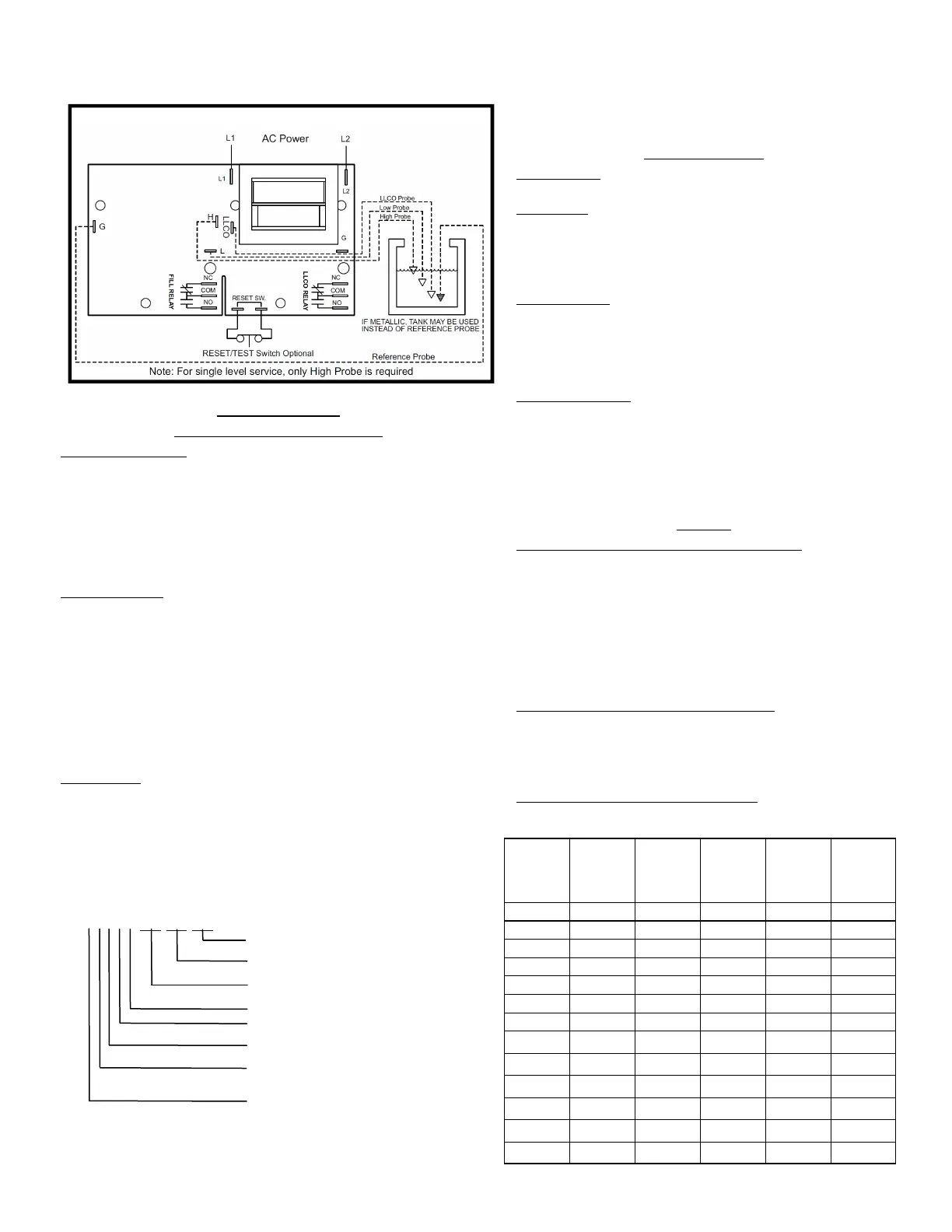
Wiring Diagram
Operation
DIRECT MODE BOTH FUNCTIONS
AUTOMATIC RESET
(Reset Switch terminals not wired) When the
liquid rises to the electrode on terminal LLCO, the control energizes,
changing state of the load contacts. (LED will be lit) The control re-
mains energized until the liquid level recedes below electrode on
terminal LLCO. The control then de-energizes, (LED will not be lit)
returning load contacts to original state. Unless otherwise specified,
there is a three second time delay on decreasing level. Liquid must
be below probe on terminal LLCO for a full three seconds before con-
trol de-energizes.
MANUAL RESET
(Normally closed pushbutton installed across reset
terminals) When the liquid rises to the electrode on terminal LLCO,
the control will remain de-energized until the pushbutton is de-
pressed. Upon Reset Swtich activation, the control will energize,
(LED will be lit) changing the state of the contacts. The control re-
mains energized until the liquid level recedes below electrode on
terminal LLCO. The control then de-energizes, (LED will not be lit)
returning load contacts to their original state. Unless otherwise spec-
ified, there is a three second time delay on decreasing level. Liquid
must be below probe on terminal LLCO for full three seconds before
control de-energizes.
Operator to wait 5 full seconds after power is
applied before pressing reset switch (if manual reset is used).
H-L Function:
When the liquid rises to the electrode on terminal H,
the associated relay energizes, changing the state of the load con-
tacts. (LED will be lit). The relay remains energized until the liquid
level recedes below electrode on terminal L. The associated relay
then de-energizes, (LED will not be lit) returning load contacts to
original state. Unless otherwise specified, there is a one half second
time delay on increasing level. Liquid must be in contact with probe
on terminal H for a full half-
second before control energizes. This function can be wired for
single level service by using only the H terminal.
INVERSE MODE
LLCO Function:
LLCO always functions in direct mode only see
above for operation.
H-L Function:
Associated relay energizes with power, (LED will be
lit) changing the state of the load contacts. When the liquid rises to
the electrode on terminal H, the relay de-energizes, returning load
contacts to shelf state. (LED will not be lit). The associated relay
remains de-energized until the liquid level recedes below electrode
on terminal L. The relay then energizes.
TEST FEATURE
Allows LLCO circuit to be tested without the need to drop the water
level in the boiler to create a dry probe condition. Holding down the
reset button for 3 seconds will allow the LLCO circuit to trip, simulat-
ing a dry probe. The controller will return to normal operation once
the reset button is pressed a second time.
LED Status Indicator
In normal operation, the LED on the control
will either be on or off depending on the controller state. On-board
microprocessors continuously monitor for fault conditions. In the
event a fault is detected, the LED will blink a pattern indicating the
fault type. If you experience an inoperable control and the LED is
blinking, attempt to leave the control in the blinking state and con-
tact the factory for assistance.
Options
Manual Reset with optional Power Outage Feature:
The Power
Outage option, used in conjunction with the Manual Reset option,
eliminates the need for a manual reset in the event of a power out-
age during normal boiler operation. With the Power Outage option, if
there is a loss of power with liquid present on the LLCO probe, the
control will self-reset (energize)
IF
liquid is still present on the LLCO
probe at the time when power is re-established. If the control did not
have liquid on the LLCO probe at the time of the power outage, or if
there is no liquid present at the time power is re-established, the
control will de-energize and remain so until liquid again rises to the
LLCO probe and the Manual Reset pushbutton is depressed.
Time Delays associated with terminals H and L :
With time delay on
increasing level, the liquid must be in contact with the high electrode
for the full duration of the time delay before control will operate. With
delay on decreasing level, the liquid must be below the low elec-
trode for the full duration of the time delay before control will oper-
ate.
Time Delays associated with terminal LLCO:
3 Second time delay
on decreasing level is standard.
DF XXXXX-XX-XX-XX
Time Delay:
(Decreasing Level) LLCO level function 3
sec. Standard
.
Time Delay:
(Decreasing Level) H-L level function 1-20
sec.
Time Delay:
(Increasing Level) H-L level function 1-20
sec.
Optional Character:
see Chart
Enclosure: 0
-none
, 1
-NEMA 1
, 4
-NEMA 4
, 7
-NEMA 7
,
12
-NEMA
Standoff Style: A
-1/16” panel,
B
-1/8” panel,
C
-
screw mount,
D
-retrofit
Supply Voltage: 1
-120VAC (+10%/-15%),
2
-240VAC
(+10%/-15%),
3
-24VAC (+10%/-15%),
5
-220VAC (+10%/
-15%),
8
-208/240VAC (187 to 242 VAC Absolute Range)
Mode/Sensitivity:
LLCO, H/L-Direct
A
-4.7K,
B
-10K,
C
-
26K,
D
-50K,
E
-100K --- LLCO, H/L-Inverse
K
-4.7K,
L
-
10K,
M
-26K,
N
-50K,
P
-100K
Reset
Function
N.C.
Pushbutton
Power
Outage
Retrofit
Plate
D
X
G
X X X
J
X X X X
K
X X
L
X X X
R
X
S
X
T
X X
W
X X
B
X
Y
X X
Z
X
A
X X X
Test
Feature
X
X
X
X
 Loading...