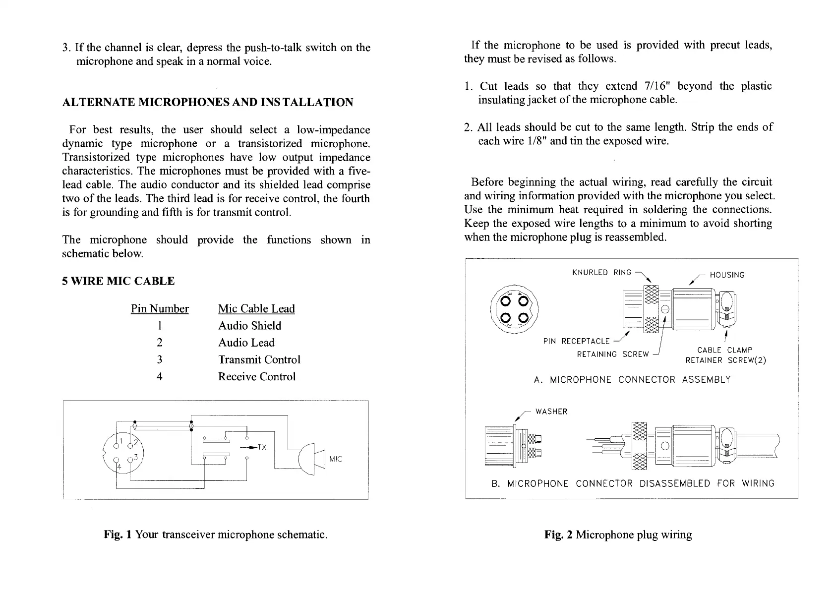
KNURLED RING
PIN RECEPTACLE
RETAINING SCREW
CABLE CLAMP
RETAINER SCREW(2)
A. MICROPHONE CONNECTOR ASSEMBLY
,- WASHER
0
E=
-
.
0
.
B. MICROPHONE CONNECTOR DISASSEMBLED FOR WIRING
3. If the channel is clear, depress the push-to-talk switch on the
microphone and speak in a normal voice.
ALTERNATE MICROPHONES AND INSTALLATION
For best results, the user should select a low-impedance
dynamic type microphone or a transistorized microphone.
Transistorized type microphones have low output impedance
characteristics. The microphones must be provided with a five-
lead cable. The audio conductor and its shielded lead comprise
two of the leads. The third lead is for receive control, the fourth
is for grounding and fifth is for transmit control.
The microphone should provide the functions shown in
schematic below.
If the microphone to be used is provided with precut leads,
they must be revised as follows.
1.
Cut leads so that they extend 7/16" beyond the plastic
insulating jacket of the microphone cable.
2.
All leads should be cut to the same length. Strip the ends of
each wire 1/8" and tin the exposed wire.
Before beginning the actual wiring, read carefully the circuit
and wiring information provided with the microphone you select.
Use the minimum heat required in soldering the connections.
Keep the exposed wire lengths to a minimum to avoid shorting
when the microphone plug is reassembled.
Mic Cable Lead
Audio Shield
Audio Lead
Transmit Control
Receive Control
5 WIRE MIC CABLE
Pin Number
2
3
4
Fig.
1
Your transceiver microphone schematic.
Fig. 2 Microphone plug wiring
 Loading...