Section 4 • Repair ProceduresJanuary 2012
Part No. 228901 GS-30 • GS-32 • GS-46 • GS-47 4 - 103
9-8
Lift Cylinder
How to Remove the Lift Cylinder
Bodily injury hazard. This
procedure requires specific repair
skills, lifting equipment and a
suitable workshop. Attempting this
procedure without these skills and
tools could result in death or
serious injury and significant
component damage. Dealer
service is strongly recommended.
When removing a hose assembly or fitting, the
fitting and/or hose end must be torqued to
specification during installation. Refer to Section 2,
Hydraulic Hose and Fitting Torque Specifications.
GS-1530, GS-1532, GS-1930 and GS-1932:
Note: Models without a pressure transducer follow
steps 1 through 23, 27 and 28.
Models equipped with a pressure transducer follow
steps 1 through 28.
1 Turn the key switch to ground control and pull
out the red Emergency Stop button to the on
position at both the ground and platform
controls.
2 Raise the platform 7 to 8 feet / 2.1 to 2.4 m.
3 Lift the safety arm, move it to the center of the
scissor arm and rotate down to a vertical
position.
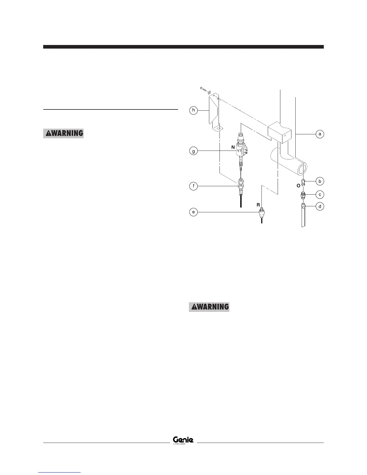
a lift cylinder
b orifice (schematic item O)
c connector fitting
d hydraulic hose
e pressure transducer (schematic R)
(if equipped)
f manual lowering cable
g solenoid valve (schematic item N)
h cable mount bracket
4 Lower the platform onto the safety arm.
Crushing hazard. Keep hands
clear of the safety arm when
lowering the platform.
5 Using a suitable lifting device, support the link
stack at the steer end of the machine.
SCISSOR COMPONENTS
 Loading...