Series II
Wall Console
Installation
Instructions
OPERATION AND FEATURES.
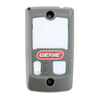
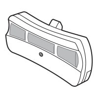
Wall console has 3 buttons and 1 indicator backlight.
Backlight
Indicator backlight will display red when wall console
is properly wired and Sure-Lock™ is OFF. When Sure-
Lock™ is ON, indicator backlight will be OFF.
Open/Close Button
This button opens and closes garage door. When
Sure-Lock™ is ON, the Open/Close button will CLOSE
door only.
NOTE: Constant button pressure in the CLOSE mode
will override STB error responses in the powerhead
and close door.
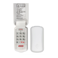
Independent Light Console Button
Use this button to turn powerhead lights ON.
Powerhead lighting will remain ON until this button is
pressed again or a door action has been completed.
Note: If opener has a Motion Detector, the sensor will
keep the powerhead lights ON as long as motion is
detected.
Sure-Lock™ Switch
When Sure-Lock™ is ON and the garage door is in
the fully closed position, the powerhead cannot be
activated by the wall console or a remote.
Note: If Sure-Lock™ is activated while the garage door is
not fully closed, the door can still be operated until the
door is in the fully closed position.
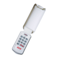
• Slide the Sure-Lock™ Switch up to activate it.
The backlight will be OFF.
• Slide the Switch down to turn Sure-Lock™ OFF.
The backlight will be ON.
Open/Close
Button
Sure-Lock™
Switch
Independent
Light Button
TOOLS REQUIRED
OPTIONAL TOOLS REQUIRED
AVERTISSEMENT
!
Vérier que l’ouvre-porte n’est pas sous
tension avant d’installer la console murale
et/ou les ls de la console murale.
39169502678 11/2014For Technical Assistance, contact the Genie Company at 1-800-35-Genie.
WARNING
!
Moving Door can cause serious injury or death.
•Wall console must be
mounted in sight of the door
at least 5 feet above oor and
clear of moving door parts.
•Keep people clear of opening
while door is moving.
•Do Not allow children to play
the remote or door opener.
If safety reverse does not work properly:
• Close door then disconnect opener using
the manual release handle. Do Not use
remote or door opener.
• Refer to door and door opener owners
manuals before attempting any repairs.
Electrical Shock can cause serious injury or death.
•Power cord must be unplugged
before attaching any wires.
•Be sure wire ends do not touch
each other or other terminals.
If you have any questions or if you need
a manual, contact the distributor or
manufacturer or the opener.
AVERTISSEMENT
!
Toute porte en déplacement peut entraîner des
blessures graves voire mortelles.
•La console murale doit être
installée en vue de la porte, à
au moins 1,5 m au-dessus du
sol et à l’écart des pièces de la
porte mobiles.
•Ne laisser personne se tenir
dans l’ouverture de la porte
pendant qu’elle est en
mouvement.
•Ne pas permettre aux
enfants de jouer avec les
télécommandes ou l’ouvre-
porte.
Si le système de sécurité à l’inversion ne
fonctionne pas correctement :
• Fermer la porte puis débrancher l’ouvre-
porte en utilisant la poignée de
déverrouillage manuel. Ne pas utiliser
la télécommande ni l’ouvre-porte.
• Se reporter aux manuels de la porte et
de l’opérateur de l’ouvre-porte avant
de tenter toute réparation.
Une décharge électrique peut provoquer des
blessures graves ou mortelles.
•S’assurer que le cordon
d’alimentation est débranché
avant de raccorder les ls.
•Les extrémités des ls ne doivent
pas se toucher entre elles ou
toucher aucune autre borne.
Si vous avez des questions ou si vous
avez besoin d’un manuel, contactez le
distributeur ou le fabricant de l’ouvre-
porte automatique.
CAUTION
!
Use only Genie® Brand Wall Consoles.
Others could cause unexpected door
operation.
WARNING
Verify there is NO power to the opener
before installing wall console and/or wall
console wires.
!
ATTENTION
Utiliser uniquement des consoles murales
Genie®. Les consoles d’une autre marque
pourraient provoquer un fonctionnement
inattendu de la porte.
!
B
W
W
1/2"
2"
Need to install new wire? Wire (P/N
35265A.S), can be purchased through
Customer Service at 1-800-35-GENIE or
from your local Genie® Dealer.
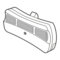
Wall Console Replacement
INSTALLING REPLACEMENT WALL CONSOLE
• Disconnect power to powerhead.
• Remove existing wall console from the
wallbyremovingmountingscrews.•
Remove wires from existing wall
console.
• Split and strip ends of wire if required
(Fig. 2).
• Fasten wire to control board screws on
back of wall console (Fig. 3):
• Connect white wire between
powerhead terminal #3 to wall console
terminal “W.” (Fig 3 & 7).
• Connect striped wire between
powerhead terminal #4 to wall console
terminal “B.” (Fig 3 & 7).
Using Previously Installed Wiring
FIG. 2.
FIG. 3.