Maintenance Manual April 2018
Quarterly Maintenance Procedures
68 S
®
Booms • Z
®
Booms Part No. 1268489GT
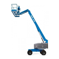
7 Place a digital level that has been calibrated to
gravity on the Y axis of the turntable.
Result: The reading at the display and digital
level is within ± 1° of each other.
Result: The reading at the display and digital
level is greater than ± 1° of each other. The
level sensor must be calibrated. Refer to
Repair Procedure in the appropriate Service
and Repair Manual for your machine, How to
Calibrate the Level Sensor.
positive degree downhill slope (ZX-135/70 shown)
negative degree uphill slope (ZX-135/70 shown)
-over hazard. If the Y axis is
to
calibrate the level sensor could
cause the machine to tip over
resulting in death or serious
injury. Refer to Repair Procedure
in the appropriate Service and
Repair Manual for your machine,
How to Calibrate the Level
Sensor
.
Q-26
Test the Secondary Boom Angle
Sensor - Z-135/70 and ZX-135/70
Genie specifications require that this procedure be
performed quarterly.
A properly functioning secondary boom angle
sensor is essential to safe machine operation. The
ECM at the ground controls (TCON) monitors the
position and angle of the secondary boom using
the signal from the secondary boom angle sensor.
The secondary boom angle sensor signal is used
to control the ramping of the secondary boom.
Note:The turntable level sensor must be tested
before starting this procedure. Refer to
Maintenance Procedure, Test the Turntable Level
Sensor.
Note: A digital level will be required to perform this
procedure.
Note: A kit is available through Genie Product
Support (Genie part number 58351). This kit
includes a digital level with a magnetic base and
cable harnesses.
Note: A properly calibrated digital level is essential
to proper machine calibration. Refer to the
manufactures calibration information.
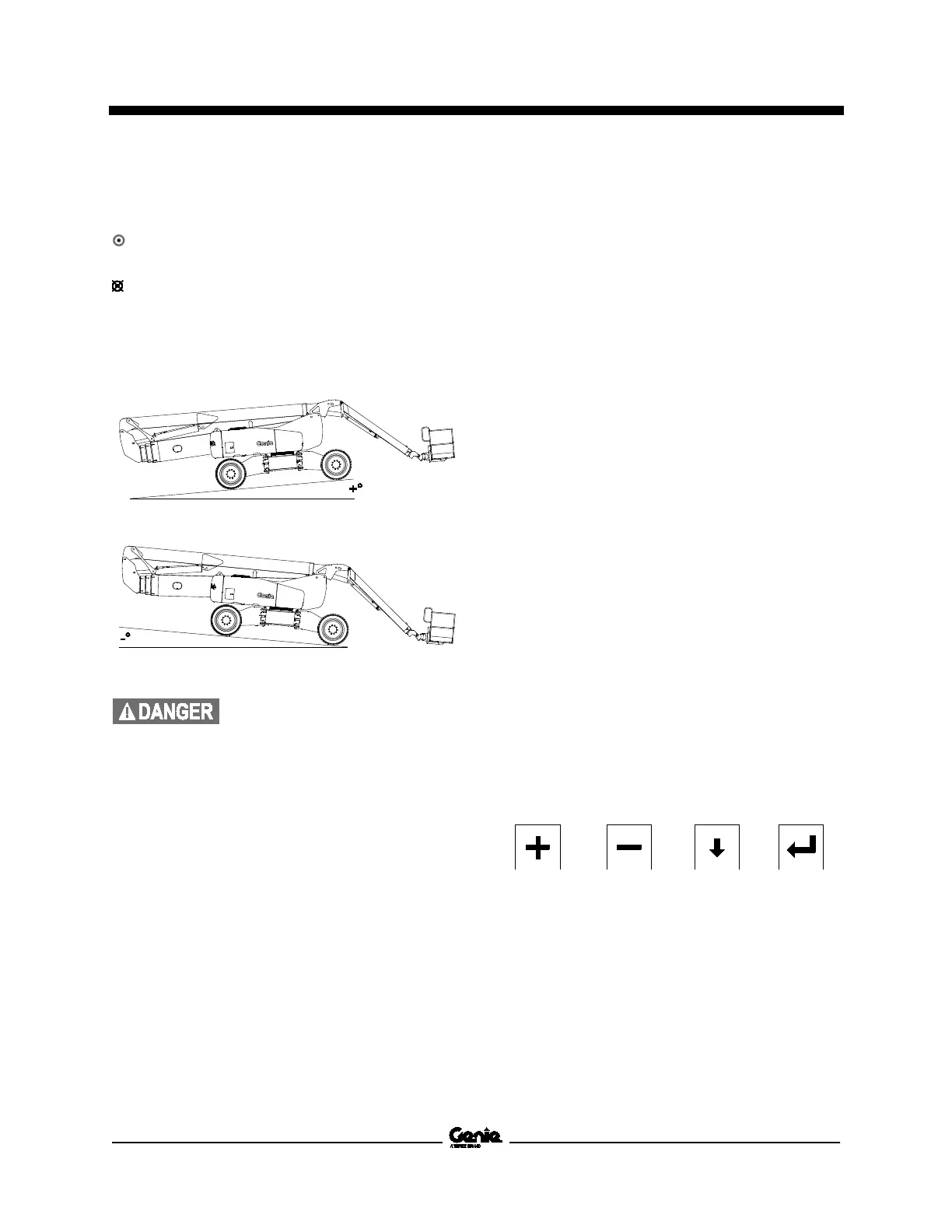
Note: Use the following chart to identify the
description of each LCD screen control button used
in this procedure.
Plus Minus Previous Enter
1 Turn the key switch to ground control and pull
out the red Emergency Stop button to the on
position at both ground and platform controls.
2 Start the engine from the ground controls.
 Loading...