No. Part No. Description No. Part No. Description
1 300660110 Screw Kit (Set of 5)
Shaft
2 200260010 Back Plate
Spring
3 203060040
Mode Selector
Assembly
6 204880020
Filter
Assembly
4 203060010 Regulator Assembly
Protecting Cap
5 204880010
Adjustment Knob
Assembly
Sponge Filter
Logo Sticker
Orifice Union
Screw
Orifice Seat
Knob 7 141742301 Gauge
Washer 8 304360010 Relief Valve
Spring 9 304660010 Main Cover
C-Clip
5
The FULL mode bypasses the regulator, and is designed for use only when high
levels of suction are needed. Care should be exercised when using this setting, as
the patient will be exposed to whatever level of suction is available at the wall inlet
(typically above 480mmHg).
A suction filter or vacuum trap assembly (GENTEC catalog #880VT) should be
used to prevent aspirate from entering the suction regulator. Typically, the suction
catheter is connected to the suction tubing, which is then connected to the inlet
fitting on the suction canister.
The canister can be connected directly to the suction regulator via DISS
connection, or, as is recommended, connected to a filter or vacuum trap, which is
then connected to the suction regulator via direct, threaded connection, suction
tubing, or DISS connector (see Figure 2).
The appropriate outlet connector (located on the back of the suction regulator)
must be used for connection to the wall inlet. The use of converting adapters (e.g.,
DISS connection to Ohio connection) should be avoided. If the suction regulator is
connected via tubing or hose assembly to the wall inlet (as occurs when the
suction regulator is attached to a mobile stand), a minimum inside hose diameter
(ID) of 5/16” (7.9mm) should be used to prevent loss of flow.
DO NOT connect the suction tubing directly from the patient to either the
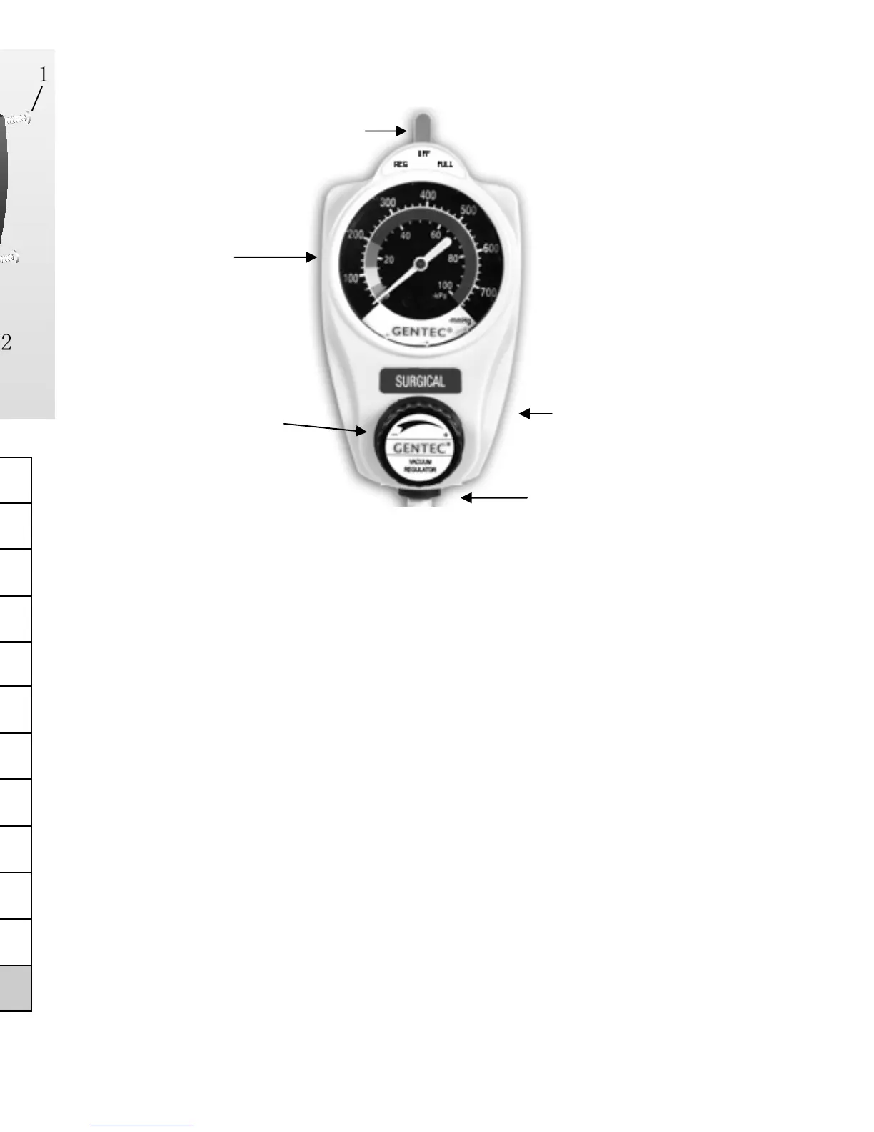
Mode Selector
Gauge
Regulator
Adjustment Knob
Outlet (in back)
Inlet (on bottom)
Figure 1 - Main Features
2
 Loading...