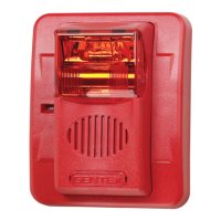
GHLF SERIES
GHSLF SERIES
ANSI/UL & CAN/ULC COMPLIANT
LOW FREQUENCY VISIBLE AND/OR AUDIBLE SIGNALING APPLIANCE
I
.
I
N
TR
O
D
U
C
TI
O
N
T
he
G
entex
m
odels
G
H
LF
and
G
H
S
LF
are
high
quality
low
frequency
audible
and/or
visible
signaling
appliances.
T
his
appliance
is
intended
to
provide
a
low
frequency
audible
or
audible/
visible,
depending
on
the
m
odel,
notification
signal
for
the
purpose
of
life
safety
and
property
protection.
T
he
G
H
S
LF
is
a
fixed
candela
unit;
the
candela
intensities
w
hich
can
be
ordered
are
15
C
d,
110C
d
and
177C
d.
T
he
G
H
S
LF
strobe
is
listed
in
com
pliance
w
ith
A
N
S
I/U
L
1971,
S
ignaling
A
ppliances
for
the
H
earing
Im
paired.
T
his
appliance
is
ideal
for
any
occupancy
that
requires
notification
appliances
per
the
applicable
building
or
fire
code
or
w
herever
dependable
alarm
s
are
required.
A
s
of
January
1,
2014
N
F
PA
72
requires
that
audible
appliances
installed
in
sleeping
areas
produce
a
low
frequency
alarm
signal.
F
or
your
inform
ation,
the
N
ational
F
ire
P
rotection
A
ssociation'
s
(N
F
PA
) S
tandard
72,
2013
E
dition,
C
hapter
18,
S
ection
18.4.5
S
leeping
A
rea
R
equirem
ents,
states
the
follow
ing:
18.4.5.3
E
ffective
January
1,
2014,
audible
appliances
provided
for
the
sleeping
areas
to
aw
aken
occupants
shall
produce
a
low
frequency
alarm
signal
that
com
plies
w
ith
the
follow
ing:
1)
T
he
alarm
signal
shall
be
a
square
w
ave
or
provide
equivalent
aw
akening
ability
2) T
he
w
ave
shall
have
a
fundam
ental
frequency
of
520H
z
±
10
percent
I
I
.
LO
C
A
TI
O
N
T
his
appliance
is
intended
for
use
in
fire
alarm
system
s
and
is
to
be
installed
in
accordance
w
ith
this
m
anual,
the
recom
m
endation
of
the
local
authorities
having
jurisdiction,
and
other
N
F
PA
docum
ents that provide standards on notification appliances for protective signaling system
s. T
he G
H
LF
and G
H
S
LF
are intended for indoor installations only; these appliances are
n
o
t listed
for
o
u
td
o
o
r
or drip proof applications.
W
all m
ounted strobe appliances shall have their entire lens at heights above the finished floor of not less than 80 in. (2m
) and not greater than 96 in. (2.4m
)**. S
pacing shall be in accordance
w
ith Table A
. If a room
configuration is not square, the room
size that w
ill entirely encom
pass the room
or subdivide the room
into m
ultiple squares shall be used. W
all m
ounted horn only
appliances shall have their tops above the finished floors at heights of not less than 90 in. (2.30m
) and below
the finished ceilings at heights of not less than 6 in. (152m
m
). D
ifferent m
ounting
heights shall be perm
itted by the A
H
J provided the sound pressure level requirem
ents of N
F
PA 72 are m
et.
I
I
I
.
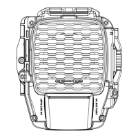
MO
UNTI
NG
,
RO
UG
H-I
N BO
X
AND RUN WI
RI
NG
T
his unit is designed for m
ounting to m
ost single gang boxes, 4" square outlet boxes, 2-gang m
asonry boxes or non-m
etallic 2-gang sw
itch boxes. C
onduit entrance to boxes should be
selected to insure sufficient w
iring clearance.
1. R
un a m
inim
um
18 gauge insulated 2 or m
ore conductor cable.
2. M
ount a box for each rem
ote signaling appliance. S
crew
bracket onto box. Insert signal into bracket and slide to the right firm
ly into the term
inal block receptacle. Insert m
ounting screw
as
show
n and tighten. C
over assem
bly w
ith the plastic housing.
N
O
T
IC
E
:
W
IR
IN
G
S
H
O
U
LD
B
E
C
O
N
N
E
C
T
E
D
TO
M
O
U
N
T
IN
G
B
R
A
C
K
E
T P
R
IO
R
TO
M
O
U
N
T
IN
G
S
IG
N
A
L. IN
C
O
M
IN
G
P
O
S
IT
IV
E
P
O
W
E
R
LE
A
D
M
U
S
T B
E
B
R
O
K
E
N
A
N
D
E
A
C
H
LE
A
D
IS
TO
B
E
IN
S
E
R
T
E
D
IN
TO
E
A
C
H
O
F
T
H
E
TO
P T
W
O
T
E
R
M
IN
A
LS
. A B
A
R
R
IE
R
IS
P
R
O
V
ID
E
D
TO
P
R
E
V
E
N
T B
O
T
H
LE
A
D
S
F
R
O
M
B
E
IN
G
P
LA
C
E
D
U
N
D
E
R
T
H
E
S
A
M
E
T
E
R
M
IN
A
L.
I
V.
AUDI
BLE
S
I
G
NALI
NG
AP
P
LI
ANCE
O
UTP
UT
w
T
he three pulse tem
poral pattern (tem
poral 3) is to be used for evacuation use only.
w
T
he standard fire alarm
evacuation signal is a three-pulse tem
poral pattern. T
he pattern consists of the follow
ing in this order:
(1) A
n “on” phase lasting 0.5 second ± 10 percent
(2) A
n “off” phase lasting 0.5 second ± 10 percent for three successive “on” periods
(3) A
n “off” phase lasting 1.5 seconds ± 10 percent
Total cycle lasts for 4 seconds ± 10 percent
w
T
he sound output for the tem
poral 3 tone is rated low
er since the tim
e the horn is off is averaged into the sound output rating. U
nits have been tested to 0°
C
, 49°
C
and 93%
hum
idity.
w T
he four pulse tem
poral pattern (tem
poral 4) is to be used for carbon m
onoxide alarm
signal use only.
w
T
he standard carbon m
onoxide alarm
is a four pulse tem
poral pattern. T
he audible carbon m
onoxide alarm
signal shall com
ply w
ith the follow
ing:
(1) S
ignals shall be a single tone pattern consisting of four cycles of 100 m
illiseconds ± 10 percent “on” and 100 m
illiseconds of ± 10 percent “off,” follow
ed by 5 seconds ±
10 percent “off.”
(2) After the initial 4 minutes of alarm, the 5-second “off” time shall be permitted to be changed to 60 seconds ± 10 percent.
w
Th
e four pu
lse temporal patte
rn
(Te
mp
o
ra
l 4
)
ca
n
o
n
ly b
e
o
b
ta
ine
d
o
n
th
is product when used in conjunction with the Gentex GTSM synchronization module or GTSM synchronization
protocol.
550-0687
Page 1
ADDITIONAL CAN/ULC LISTED PRODUCT INFORMATION IS FOUND ON PAGE 4
Horn Decibel Levels:
Reverberant Room
24VDC Nominal Horn
Current Ratings (mA)
Horn Current Ratings (UL Max)
2
Over Input Voltage Range of 16-33V (mA)
Horn Mode
Minimum SPL
at 10Ft. Per
ANSI/UL 464
(NORMAL)
Minimum SPL
at 10Ft. Per
ANSI/UL 464
(LOUD)
24VDC
Operating
Current
(NORMAL)
24VDC
Operating
Current
(LOUD)
24VFWR
Operating
Current
(NORMAL)
24VFWR
Operating
Current
(LOUD)
Regulated
24VDC Max.
Operating
Current
(NORMAL)
Regulated
24VDC Max.
Operating
Current
(LOUD)
Regulated
24VFWR Max.
Operating
Current
(NORMAL)
Regulated
24VFWR Max.
Operating
Current
(LOUD)
Temporal 3 520 Hz 77.8 dBA 79.8 dBA 72.1 mA 120.1 mA 104.6 mA 158.4 mA 99.4 mA 155.8 mA 152.1 mA 213.5 mA
Temporal 4 520 Hz
1
81.5 dBA 83.4 dBA 75.9 mA 116.0 mA 108.1 mA 182.0 mA 100.1 mA 157.2 mA 163.1 mA 235.2 mA
GHLF PRODUCT INFORMATION
1
Temporal 4 520 Hz measured per ANSI/UL 2075
2
Recommended
GHLF Horn Decibel Levels and Current Ratings