41
Error, alarm and warning messages
Indication, diagnosis and remedy
Attention
Before carrying out the fault diagnosis please check:
Supply voltage:
Is the equipment supplied with the voltage specified on the name plate?
Wiring:
Is the wiring in accordance with the wiring diagram?
Attention
n
Please refer to the installation & operating manuals for LRG 12-2, LRG 16-4, LRG 16-9,
LRG 17-1, LRG 19-1, TRG 5-.. and LRGT 1.-.. for further fault-finding and troubleshooting.
If a malfunction occurs in the conductivity controller, MIN and MAX alarms will be
triggered and the equipment is restarted.
Should this happen over and over again, replace the equipment with a new one.
Note
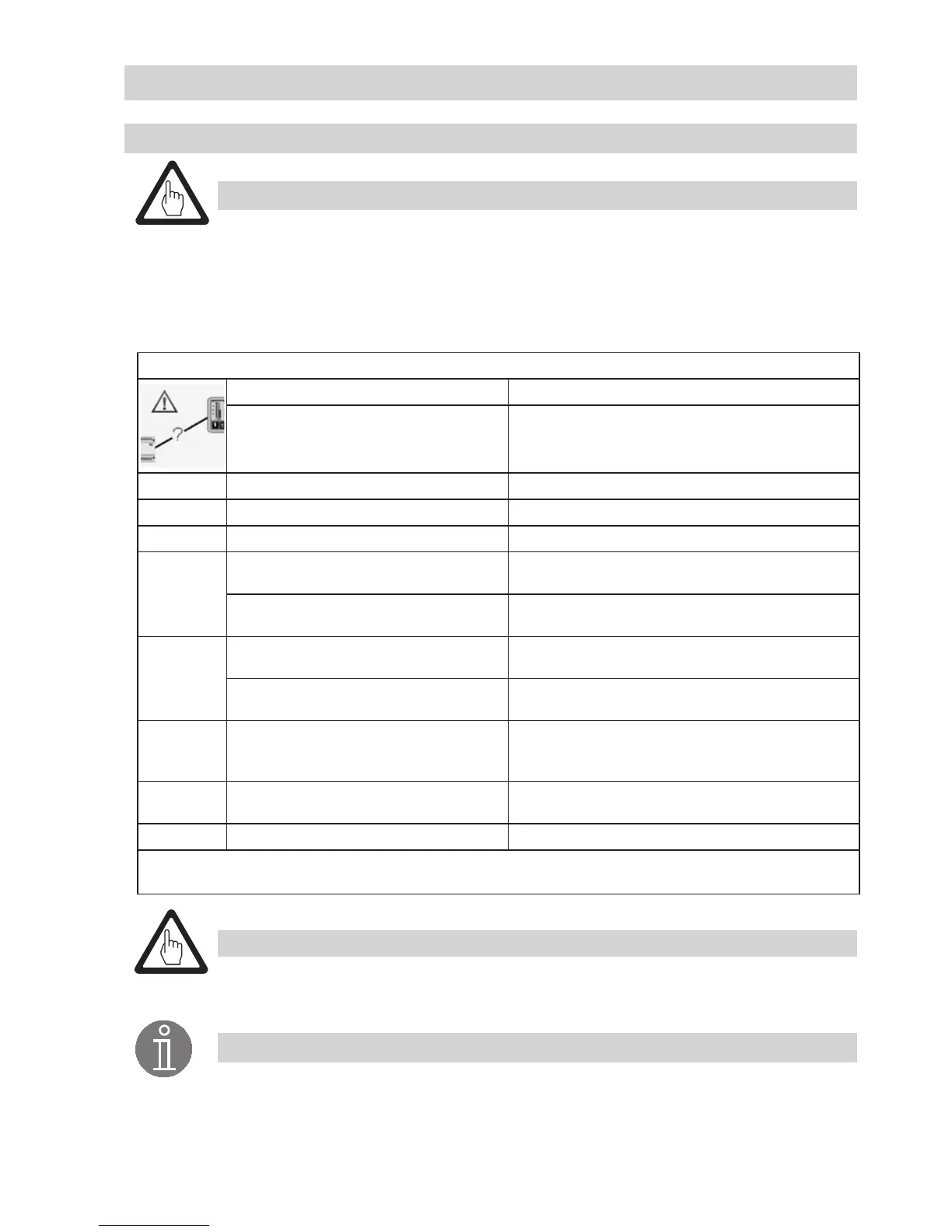
Alarm list / window
Status / error Remedy
Communication LRR/URB disrupted
Check electrical connection. Switch supply voltage off
and on again to re-start the equipment.
Code
A.001 MAX switchpoint exceeded
A.002 Value below MIN switchpoint
E.005
Conductivity electrode defective,
measuring voltage < 0.5 VDC
Check conductivity electrode and, if necessary, replace
it. Check electrical connection.
Conductivity transmitter defective,
measuring current < 4 mA
Check conductivity transmitter and, if necessary,
replace it. Check electrical connection.
E.006
Conductivity electrode defective,
measuring voltage > 7 VDC
Check conductivity electrode and, if necessary, replace
it. Check electrical connection. Check boiler water.
Conductivity transmitter defective,
measuring current > 20 mA
Check conductivity transmitter and, if necessary,
replace it. Check electrical connection.
E.101
If continuous blowdown valve is equipped
with a potentiometer: Calibration values 0
and 100 % have been reversed.
Re-calibrate the potentiometer in the continuous
blowdown valve.
E.102
Beginning and end of measuring range
have been reversed.
Re-adjust the measuring range.
E.103 MIN switchpoint above MAX switchpoint Re-adjust the switchpoints.
In the event of a malfunction (E. xxx) a MIN and MAX alarm will be triggered
and the continuous blowdown valve closes.

 Loading...


