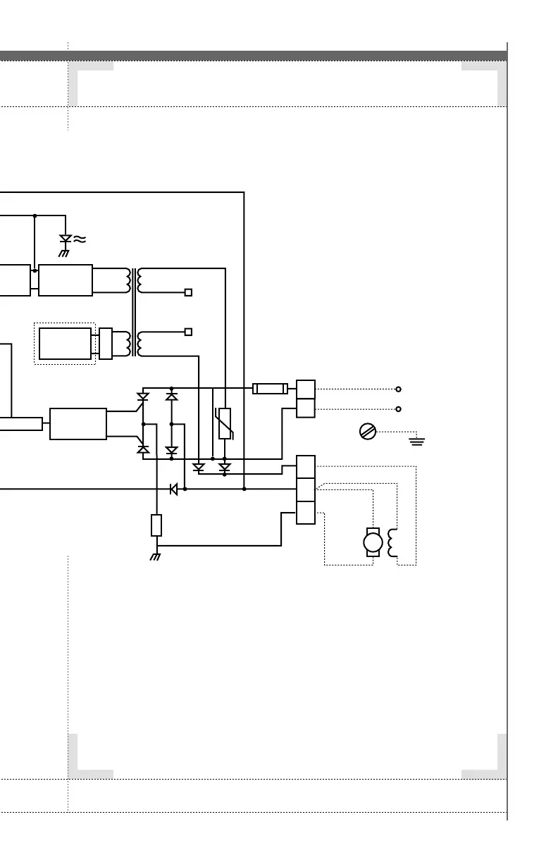
1. Refer to Installation Instructions, and Wiring Instruction for
further information
2. Must be removed for tachometer feedback.
3. When optional isolation is used the RUN LED will light on the
isolation board.
4. Factory set at OVDC.
5. Factory set for 90VDC for 120V controllers, and 180VDC for
240V controllers.
6. Factory set for 100% of controller rating.
7. Factory set for zero compensation.
8. Factory set for 1/2 second.
9. Factory set for 1/2 second.
10. If half wave field is required, connect between F1 and L2.
11. Shielded cable recommended but not required.
1110
G R A H A M M O T O R S A N D C O N T R O L S V A R I S P E E D
®
A 2 0 0 0R E L I A B I L I T Y + C O M P A T I B I L I T Y S I N C E 1 9 3 5
NOTES
>
1
TB2
Run/Stop
Switch
(Close to run)
Max. Speed (5)
Min. Speed (4)
Accel
(9)
Decel
(8)
Run
Indicator
(Yellow)
(3)
5K
Speed
Pot
DC
Tach
(If used)
+
–
+
–
+12V
+12V
(1) RA (2)
T
2
3
4
5
6
+12V
Speed
Error
Inte-
grator
Zero
Crossing
Detector
Regulated
Power
Supply
Diode
Bridge
Option
Board
16
PIN
DIP
Socket
Gate 1
Gate 2
120/240V
SCR1 D1
Fuse
TB1
AC
Line
Earth
Ground
DC
Motor
Field
(If Used)
(10)
L1
SCR2
Field Diodes
Current
Shunt
4.5AMP-16AMP
OV
D2
AC
AC
Comparator
Current
Limit (I-LIM)
Indicator
(Red)
Current
F.B.
IR Comp
(7)
I-LIM
(6)
Power
Indicator
(Green)
Pulse
Generator
Driver
TB3
F1
F2
A2
A1
DC
Motor
L2
Artisan Technology Group - Quality Instrumentation ... Guaranteed | (888) 88-SOURCE | www.artisantg.com