156
G R A H A M M O T O R S A N D C O N T R O L S V A R I S P E E D
®
A 2 0 0 0R E L I A B I L I T Y + C O M P A T I B I L I T Y S I N C E 1 9 3 5
Use caution during these procedures because line voltage will
be present on the power and motor terminals as well as on the
printed circuit board when the power is on.
NOTE: If, at any stage of this procedure, the control does not act
as indicated, refer to Troubleshooting section.
1. With AC power off, recheck to be sure that all power and
control connections are properly secured and connected
according to the installation instructions.
2. With enclosed units, be sure that the ribbon cable front the
cover is plugged into S1 on the A2000 PC board (or, if used,
S3 on the Isolation Option PC board).
3. Set the speed pot to minimum speed (CCW) and place the
ON/OFF switch in the OFF position.
4. Apply power to the control and confirm that the POWER ON
(green) LED glows. If the LED does not glow refer to the
Troubleshooting section.
NOTE: On enclosed versions the indicators in the cover glow.
The indicators on the printed circuit assembly are disabled by
having the cover connected.
5. Place ON/OFF switch in the ON position. The RUN (yellow)
LED should glow, but the motor should not turn.
6. Slowly rotate speed pot in a clockwise direction. Motor
should begin turning. Continue to rotate speed pot until
desired motor speed is achieved.
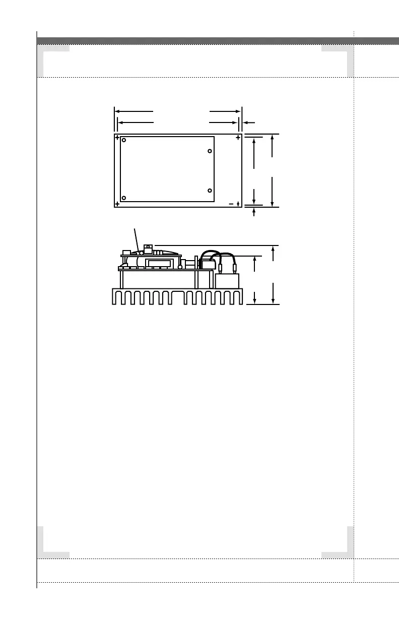
SET-UP PROCEDUREHEAT SINK VERSION
>>
Drive shown without protective barrier.
8.00 (203)
7.38 (187)
(8)
0.31
4.31
(109)
0.31
(8)
Optional isolation board
3.15
(80)
4.05
(103)
4.94
(125)
Artisan Technology Group - Quality Instrumentation ... Guaranteed | (888) 88-SOURCE | www.artisantg.com