ActuAtor with integrAted regulAtor, K282
for r298 And r298n mixing vAlve
0262EN May 2013 047U31758
2
ISO
9001
0006/7
ISO
14001
0032A/2
OHSAS
18001
0064L/0
Addressing
The addressing through microswitch with several ways is not relevant when
K282 actuator is used as single device (stand-alone conguration): it is not
necessary to make any conguration in this application.
The addressing through microswitch with several ways is vital for the correct
conguration of the device in those applications in which the actuator is used
in combination with KM20x network controller.
All microswitch sliders are positioned on “OFF” (side with 1-8 numbers)
on delivery. K282 actuator uses selectors from 1 to 6 to assign an address
between 0 and 31: check the address to assign on the design documentation
of the system.
Signalling elements
The led on the frontal side of K282 actuator provides two kinds of information:
the application type, stand-alone or with bus signal network connection to
KM203 network controller and summer/winter mode set to regulate the
delivery temperature.
Fixed red: indicates stand-alone functioning in WINTER mode.
Fixed green: indicates stand-alone functioning in SUMMER mode.
Flashing red: indicates the functioning in combination with KM203 network
controller in WINTER mode.
Flashing green: indicates the functioning in combination with KM203
network controller in SUMMER mode.
Flashing alternate red/green: indicates that K282 actuator, used in combination
with KM203 network controller, is no more supervised by KM203 because of
an anomaly (deactivation of supply to network controller or communication
problems on bus network).
The operating set has become the one set on the rotating potentiometer and
the real mode, that is the one imposed by the supervisor, is not coherent with
the operating mode imposed by the manual selector on the frontal side. With
this signal, it is recommended to check the correct supply to the network
controller and the correct functionality of bus network.
When 24 V~ supply is activated to K282 actuator, the integrated electronic
regulator starts a cycle of adjustment in which the stem of the actuator is
led to complete by-pass position (the whole stem has gone back in the
actuator body).
Connection to bus
Data between K282 actuator and KM203 network controller are transfered
through the system bus (connection to primary bus) by using RT+, RT- and
Com terminals. In addition, the supply for the communication function is
carried through the system bus by using V and Com terminals. Max. 3 K282
actuators can be connected to KM203 network controller.
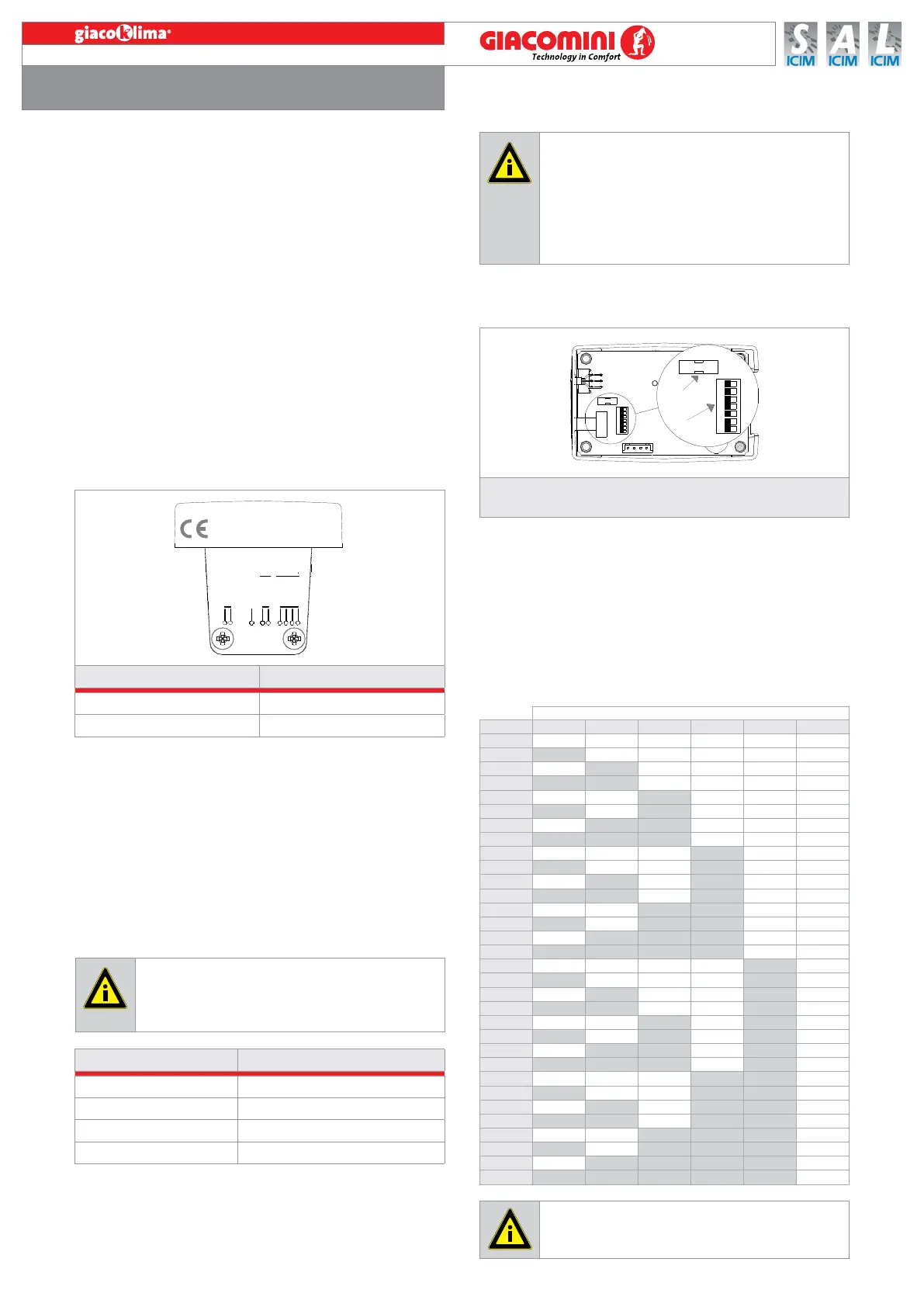
1
2
1 2 3 4 6 7 8
1 Jumper for manual control (open ring) of the actuator
2 8 way microswitch for actuator addressing
K282X002 24V
50/60 Hz
5VA
SENSOR
DELIVERY TEMP.
BLU
WHITE
GREEN
YELLOW
V
Com
RT-
RT+
GRAY
24V
BUS
BROWN
SHUTOFF PINK
Conductor color Function
BROW 24 V~ supply connection
GRAY 24 V~ supply connection
Conductor color Function
YELLOW RT+ Signal (RS485 standard)
GREEN RT- Signal (RS485 standard)
WHITE Com Common (signal + supply)
BLUE V SELV supply
Caution!
Before connecting K282 actuator, make sure that network tension IS
NOT CONNECTED and that it corresponds to the one written on the
back of the device (24 V~). The device must be installed by qualied
sta only.
Caution!
Before the connection to the system bus, make sure that
KM203 network controller is not supplied, not to damage the
communication module of K282 actuator. In case more than 3
actuators are connected to KM20x controller (through primary bus),
it is necessary to provide a separated supply of the devices. The bus
cable of K282 actuator must be placed in a canalization with an
electrical protective covering independent from canalizations that
carry network tension or that control actuators.
Position of microswitch ways
Ind. 1 2 3 4 5 6
0 OFF OFF OFF OFF OFF OFF
1 ON OFF OFF OFF OFF OFF
2 OFF ON OFF OFF OFF OFF
3 ON ON OFF OFF OFF OFF
4 OFF OFF ON OFF OFF OFF
5 ON OFF ON OFF OFF OFF
6 OFF ON ON OFF OFF OFF
7 ON ON ON OFF OFF OFF
8 OFF OFF OFF ON OFF OFF
9 ON OFF OFF ON OFF OFF
10 OFF ON OFF ON OFF OFF
11 ON ON OFF ON OFF OFF
12 OFF OFF ON ON OFF OFF
13 ON OFF ON ON OFF OFF
14 OFF ON ON ON OFF OFF
15 ON ON ON ON OFF OFF
16 OFF OFF OFF OFF ON OFF
17 ON OFF OFF OFF ON OFF
18 OFF ON OFF OFF ON OFF
19 ON ON OFF OFF ON OFF
20 OFF OFF ON OFF ON OFF
21 ON OFF ON OFF ON OFF
22 OFF ON ON OFF ON OFF
23 ON ON ON OFF ON OFF
24 OFF OFF OFF ON ON OFF
25 ON OFF OFF ON ON OFF
26 OFF ON OFF ON ON OFF
27 ON ON OFF ON ON OFF
28 OFF OFF ON ON ON OFF
29 ON OFF ON ON ON OFF
30 OFF ON ON ON ON OFF
31 ON ON ON ON ON OFF
Caution!
Make sure that the assigned address is correct: it is not possible
to have two devices with the same address in the same system.

 Loading...